A combined oilfield water injection well layered acidification device

An oil field water injection, combined technology, applied in wellbore/well components, construction, earth-moving drilling, etc., can solve the problems of not distinguishing the clogging of sand control pipes, different times of acidizing and unblocking, insufficient unblocking time, etc. The effect of maximum utilization, reduction of acidification time, and extension of acidification time

Active Publication Date: 2021-09-24
西安步锐石油工程技术有限公司
View PDF0 Cites 0 Cited by
  • Summary
  • Abstract
  • Description
  • Claims
  • Application Information

AI Technical Summary

Problems solved by technology

However, this technology does not distinguish the clogging of sand control pipes at different formation heights, so the whole pipe unblocking operation is often used
However, in actual production, the clogging conditions of different sections of the sand control pipe are different, some positions may not be clogged, and some positions may be severely clogged, and the required acidification and plugging removal time is also different. However, it lacks pertinence, which may lead to waste of acidizing fluid at positions that do not need to be unblocked, and insufficient time for unblocking at positions that need to be unblocked

Method used


Image

  • A combined oilfield water injection well layered acidification device
  • A combined oilfield water injection well layered acidification device
  • A combined oilfield water injection well layered acidification device

Examples


Embodiment 1

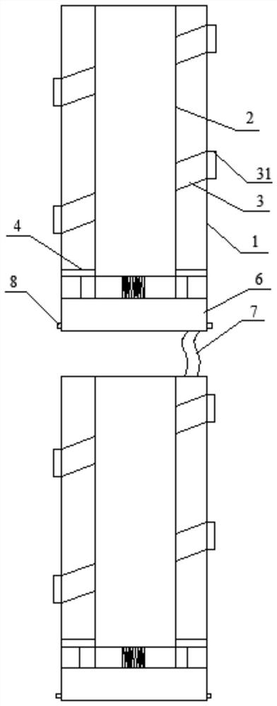
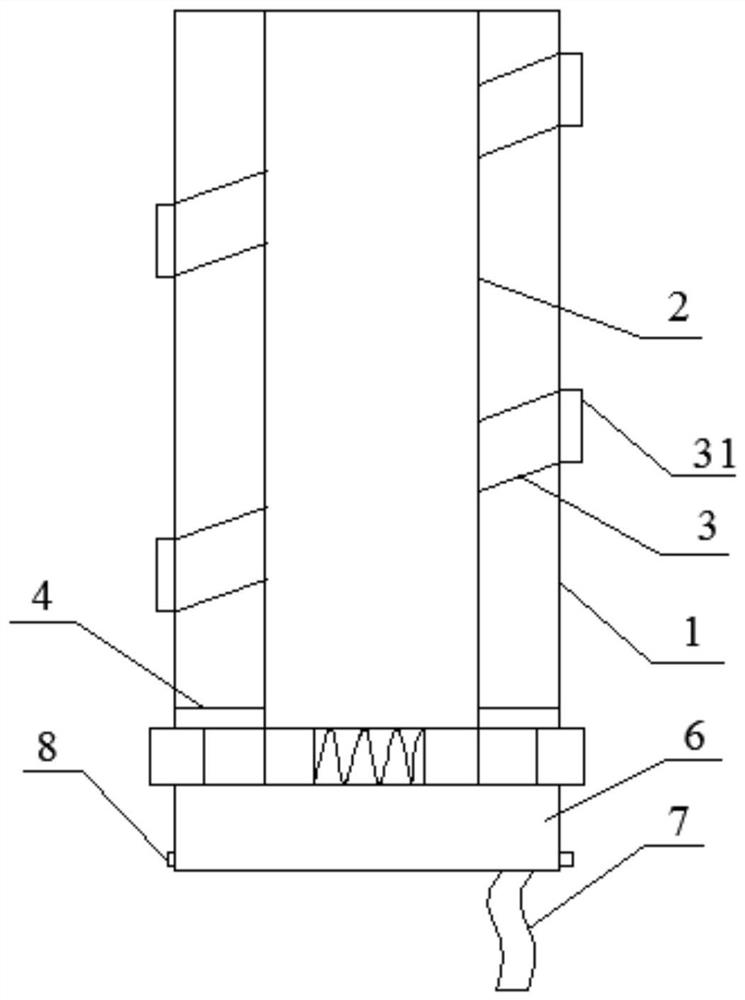
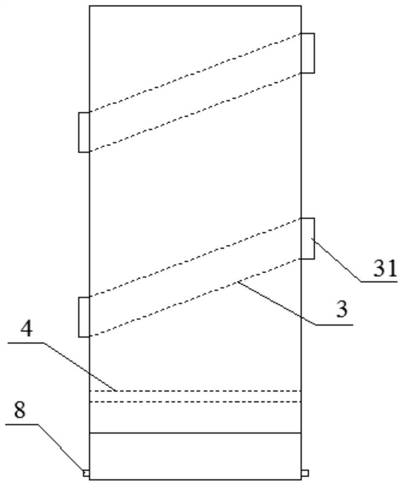
[0047] A combined oilfield water injection well layered acidification device, such as Figure 1-4 As shown, it includes several acidizing units, and the adjacent acidizing units are detachably connected. These acidizing units are used to be positioned at different formation heights in the sand control pipe in the oilfield water injection well. They can be connected and used, or they can be distributed discretely in the sand control pipe It is used in order to achieve the plugging effect of sand control pipes at different formation heights, with strong pertinence and high efficiency, and it can also save acidizing fluid.

[0048] The acidizing unit includes: an outer pipe 1, which is used to be positioned at a specific formation height in the sand control pipe in the water injection well of the oil field, and an inner pipe 2 is coaxially sleeved inside the outer pipe 1, and the outer pipe 1 and There is a cavity between the inner pipes 2 where the acidizing liquid injection pip...

Embodiment 2

[0057] A combined layered acidification device for water injection wells in oilfields, the structure of which is basically the same as that of Example 1, the difference is that the telescopic air bag 51 is provided with a number of micropores, and the interior of the telescopic air bag 51 is filled with water-absorbing materials, which are sprayed onto sand control The excess acidizing liquid on the pipe flows into the water-absorbing material along its inner wall and is absorbed to prevent excessive acidizing liquid from stagnating in the formation. The water-absorbing material chooses a material with physical adsorption effect, which can analyze and recover the acidizing liquid and achieve the effect of resource recycling. For example, the sponge material can absorb water and squeeze water out.

[0058] There is also a distance of 0-2 mm between the connecting rigid pipe 6 and the positioning assembly, so as to receive excess acidizing fluid leaking from the telescopic air ba...

Embodiment 3

[0060] A combined layered acidification device for oilfield water injection wells, basically the same structure as in Example 1, the difference is that the structure of the positioning assembly is as follows Figure 5 As shown, it includes an electric telescopic rod 5, an inner telescopic ring and an outer telescopic ring that are sequentially sleeved from the inside to the outside. The inner telescopic ring is surrounded by several inner arc-shaped plates 52, and the outer telescopic ring is surrounded by several outer arc-shaped plates 53. The electric telescopic rod 5, the inner arc-shaped plates 52, the outer The number of arc-shaped plates 53 is the same, and they correspond to each other. The positions of the inner arc-shaped plate 52 and the outer arc-shaped plate 53 correspond radially, the fixed end of the electric telescopic rod 5 is fixedly installed on the outer wall of the inner tube 2, and the movable end is fixedly installed on the corresponding The inner side ...


PUM


Abstract

The invention belongs to the technical field of oil field acidizing equipment, and in particular relates to a combined layered acidizing device for oilfield water injection wells, which includes several acidizing units detachably connected; the acidizing unit includes an outer pipe and an inner pipe, and the inner pipe is coaxially sleeved inside the outer pipe The acidizing liquid injection pipe is arranged in the cavity left between the outer pipe and the inner pipe; the nozzle, whose liquid inlet end is connected with the acidizing liquid injection pipe, and the liquid outlet end is inlaid on the outer pipe wall; the ring connection The lower end of the inner tube is exposed to the outside of the cavity, and the connecting plate is in sealing connection with the bottom of the cavity; the telescopic positioning component and the joint component are installed on the outer periphery of the lower end of the inner tube and are located under the connecting plate. The present invention sets several detachably connected acidizing units for positioning at different formation heights in sand control pipes in oil field water injection wells. They can be connected or used in discrete distribution, and have a blocking effect on sand control pipes of different formation heights, with strong pertinence and high efficiency. High, can also save acidizing fluid.

Description

technical field [0001] The invention belongs to the technical field of oilfield acidification equipment, and in particular relates to a combined layered acidification device for oilfield water injection wells. Background technique [0002] Oil field water injection or oil production mainly depends on the sand control pipe installed in the water injection well, and the oil penetrates into the sand control pipe and is then mined. During the long-term production process, the sand control pipe will be blocked, and acidification and plugging removal are required to restore and improve the permeability of the formation, so as to reduce the resistance of oil flowing into the well or the resistance of water injection, so as to increase the production of the oil well. Purpose of well injection. [0003] In the prior art, sand control pipe plant lumen flushing and rotary water jet unblocking processes are often used, and the acidizing solution penetrates into the formation through fl...

Claims


Application Information

Patent Timeline
Patent Type & Authority Patents(China)
IPC IPC(8): E21B37/06E21B41/00E21B47/095
CPCE21B37/06E21B41/0057E21B41/0078
Inventor 郭锦涛杨静权鹏飞何洲
Owner 西安步锐石油工程技术有限公司
Why Eureka
Try Eureka