
Welding wire width measuring device

A width measurement and welding wire technology, which is applied in the field of welding wire width measurement devices, can solve the problems of thickness measurement influence, time-consuming and laborious, and inability to ensure that the welding wire meets the standards, so as to reduce the scrap rate and material loss.

Pending Publication Date: 2021-01-01
中国计量大学上虞高等研究院有限公司 +1
View PDF0 Cites 0 Cited by
  • Summary
  • Abstract
  • Description
  • Claims
  • Application Information

AI Technical Summary

Problems solved by technology

However, during the production process, the flattening machine will produce deformation that is difficult to detect with the naked eye as the use time increases, which will cause the pressed solder to fail to meet the standard
At the same time, due to the marking link in the existing production line process, the marking on the solder has an impact on the direct thickness measurement
[0004] At this stage, the detection of welding wire standards is still in the manual sampling inspection. This method cannot guarantee that every package of welding wire produced meets the standards. At the same time, manual inspection has the disadvantages of time-consuming, laborious and large errors.
[0005] Therefore, it is necessary to design a continuous and high-precision welding wire width measuring device to solve the above-mentioned problems of large errors in manual inspection and the inability to ensure that each section of welding wire meets the standard.

Method used


Image

  • Welding wire width measuring device
  • Welding wire width measuring device
  • Welding wire width measuring device

Examples


Embodiment Construction

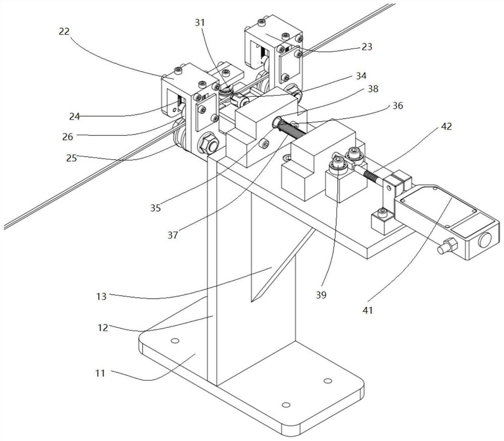
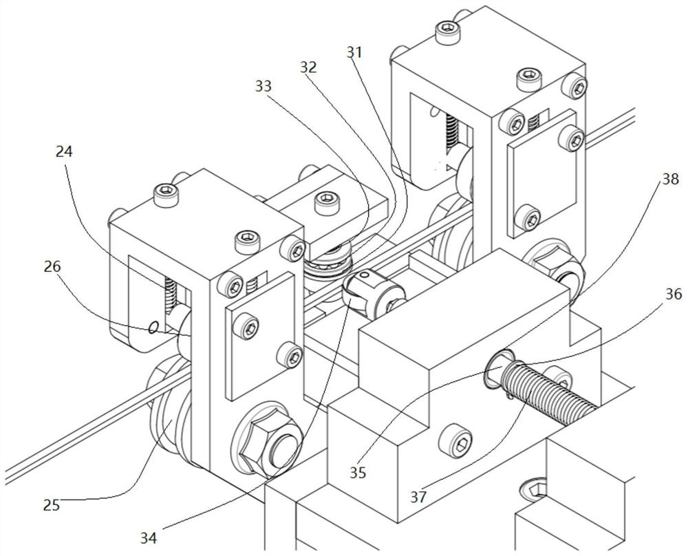
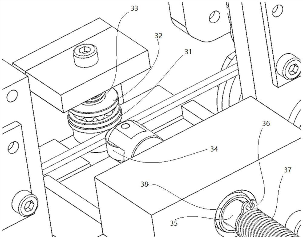
[0019] Such as figure 1 As shown, a welding wire width measuring device 100 includes a base 10 , a limiting device 20 , a width measuring device 30 , and a sensing device 40 . The base 10 is used to provide a stable horizontal surface suitable for the height of the production line to mount the rest of the wire width measuring device. The limiting device 20 is fixed on the vertical plane provided by the side surface of the base to limit the electrode so that the electrode channel is parallel to the horizontal plane provided by the base 10, and the width measuring device 30 and the sensing device 40 are fixedly installed on the base 10. On the horizontal plane, the width measuring device 30 is used to measure the width of the passing welding wire in real time to provide enough sampling data for the measurement of the welding wire width, and the sensing device 40 is used to convert the measured welding wire width into data and upload it for processing.

[0020] Such as figure 1...


PUM


Abstract

The invention relates to a welding wire width measuring device which comprises a base, a limiting device, a width measuring device and a sensing device. The limiting device is used for limiting an introduced welding rod to keep the welding rod straight, the width measuring device is used for measuring the width of the welding rod, and the sensing device is used for reading width data of the welding rod. By measuring the width of the welding wire in a production process in real time, an effect of measuring the thickness of the produced welding rod is achieved. Meanwhile, equipment for producingthe welding wires can be adjusted in time through feedback adjustment so that the thickness of the produced welding rods meets a production standard, a rejection rate is reduced, and material lossesare decreased. The measurement precision can reach + / -40 mum.

Description

technical field [0001] The invention relates to a welding wire width measuring device Background technique [0002] When the era enters the era of mechanized production, for the welding process, a problem arises after the use of automatic welding equipment to increase the welding output, that is, the use of electrodes with uneven thickness will have a significant impact on the welding effect. Therefore, in order to avoid this situation and to meet the export welding wire standards, it is necessary to produce welding wires that meet the standards. [0003] In the production process of solder, a series of processes such as heating, drawing, flattening, marking and subsequent cleaning of the initial welding wire are required to obtain the final solder. However, during the production process, the flattening machine will produce deformation that is difficult to detect with the naked eye as the use time increases, which will cause the pressed solder to fail to meet the standard. ...

Claims


Application Information

Patent Timeline
IPC IPC(8): G01B7/02
CPCG01B7/02
Inventor 柯海森丰峰田俊李声亮严天宏
Owner 中国计量大学上虞高等研究院有限公司
Learn More