Direct-current charging pile testing device

A technology for DC charging piles and testing devices, which is applied to measuring devices, measuring device shells, short-circuit tests, etc., and can solve the problems of easy electric shock, inconvenient use of users, and damage to testing devices, and is easy to fix and carry, and easy to maintain and the effect of using and avoiding damage

Active Publication Date: 2021-01-01
SUZHOU TRACEABILITY STANDARD CERTIFICATION & INSPECTION CO LTD
View PDF10 Cites 0 Cited by
  • Summary
  • Abstract
  • Description
  • Claims
  • Application Information

AI Technical Summary

Problems solved by technology

[0002] In recent years, with the rapid development of the number of electric vehicles, the need to strengthen the full life cycle testing and management of charging facilities has become increasingly prominent. However, at present, there is a lack of professional testing equipment for on-site testing of charging facilities, and testers usually use electric vehicles as loads to carry out tests , the existing authorized announcement number is CN206223824U DC charging pile test device, the first cable, the second cable, the branch interface device, the first socket, the second socket, the first end of the branch interface device passes through the first The cable is connected to the DC charging pile, and the second end is connected to the DC load or electric vehicle through the second cable. It is compatible with electric vehicles and DC loads. The whole process of charging the DC charging pile is tested to achieve the whole process of charging the DC charging pile of the electric vehicle. The technical effect of safe and fast testing, but in this way, the leakage test of the DC charging pile cannot be performed, which is prone to electric shock, which brings danger to the staff, and it is inconvenient for the test device to be carried and shock-absorbed, resulting in damage to the test device, which is inconvenient user use

Method used


Image

  • Direct-current charging pile testing device
  • Direct-current charging pile testing device
  • Direct-current charging pile testing device

Examples


Embodiment Construction

[0025] The following will clearly and completely describe the technical solutions in the embodiments of the present invention with reference to the accompanying drawings in the embodiments of the present invention. Obviously, the described embodiments are only some, not all, embodiments of the present invention. Based on the embodiments of the present invention, all other embodiments obtained by persons of ordinary skill in the art without making creative efforts belong to the protection scope of the present invention.

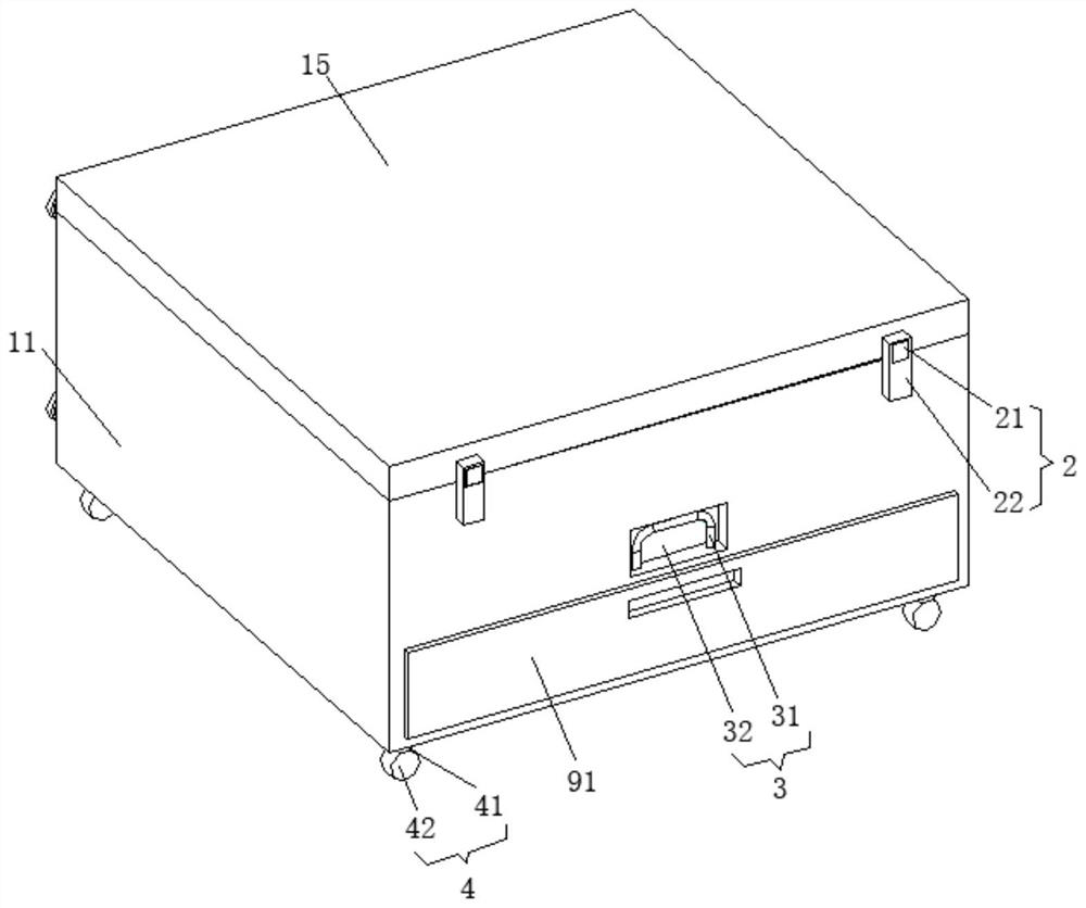
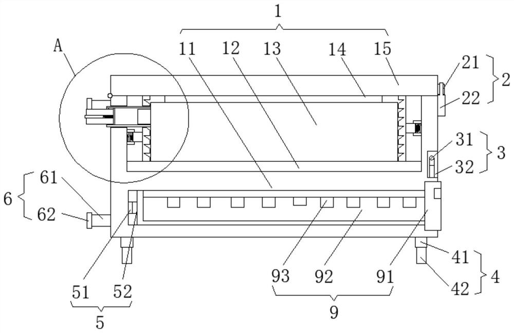
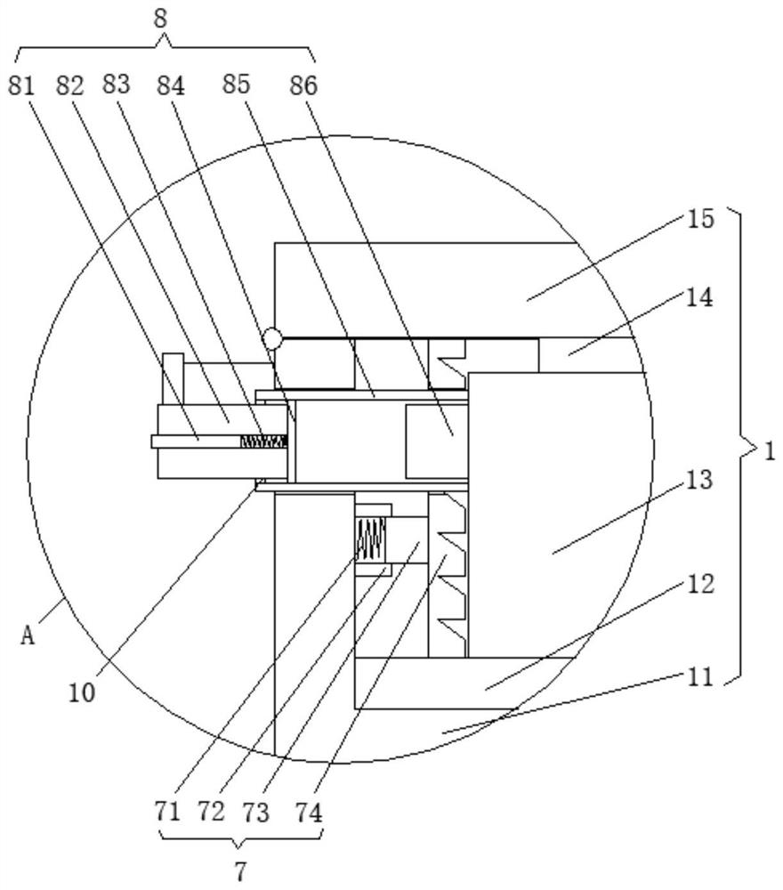
[0026] see Figure 1-3, the present invention provides a technical solution: a DC charging pile test device, including a shock absorbing mechanism 1, a clamping mechanism 7 and a leakage test mechanism 8; shock absorbing mechanism 1: it includes a housing 11, the front side of the housing 11 A lifting mechanism 3 is provided, a moving mechanism 4 is provided on the bottom side of the housing 11, a support mechanism 6 is provided on the rear side of the housing...


PUM


Abstract

The invention discloses a direct-current charging pile testing device which comprises a damping mechanism, a clamping mechanism and an electric leakage testing mechanism. The damping mechanism comprises a shell, a lifting mechanism is arranged at the front side of the shell, and a moving mechanism is arranged at the bottom side of the shell; a supporting mechanism is arranged at the rear side of the shell, a first damping rubber is arranged at the bottom side in the shell, a testing machine is placed on the first damping rubber, and a sealing cover is hinged to the upper surface of the shell;second damping rubber is arranged at the bottom side in the sealing cover and is located on the upper surface of the testing machine, and a clamping mechanism is arranged at the front side of the shell and the front side of the sealing cover; and the clamping mechanism comprises eight first fixing sleeves. The direct-current charging pile testing device can carry out electric leakage testing on adirect-current charging pile, electric shock is avoided, dangers to workers are prevented; moreover, the testing device can be conveniently carried and damped, damage to the testing device is prevented, and the direct-current charging pile testing device can be conveniently used by a user.

Description

technical field [0001] The invention relates to the technical field of charging pile testing, in particular to a DC charging pile testing device. Background technique [0002] In recent years, with the rapid development of the number of electric vehicles, the need to strengthen the full life cycle testing and management of charging facilities has become increasingly prominent. However, there is currently a lack of professional testing equipment for on-site testing of charging facilities, and testers usually use electric vehicles as loads to carry out tests , the existing authorized announcement number is CN206223824U DC charging pile test device, the first cable, the second cable, the branch interface device, the first socket, the second socket, the first end of the branch interface device passes through the first The cable is connected to the DC charging pile, and the second end is connected to the DC load or electric vehicle through the second cable. It is compatible with ...

Claims


Application Information

Patent Timeline
IPC IPC(8): G01R31/52G01R1/04F16F15/08
CPCG01R31/52G01R1/04G01R1/0425F16F15/085Y02T10/70Y02T10/7072
Inventor 张菡莉
Owner SUZHOU TRACEABILITY STANDARD CERTIFICATION & INSPECTION CO LTD
Why Eureka
Try Eureka