MIMO antenna and mobile communication equipment

An antenna, antenna group technology, applied in the direction of antenna, antenna coupling, resonant antenna, etc.

Pending Publication Date: 2021-01-01
昆山亿趣信息技术研究院有限公司
View PDF0 Cites 1 Cited by
  • Summary
  • Abstract
  • Description
  • Claims
  • Application Information

AI Technical Summary

Problems solved by technology

[0004] The purpose of the present invention is to provide a MIMO antenna and mobile communication equip

Method used


Image

  • MIMO antenna and mobile communication equipment
  • MIMO antenna and mobile communication equipment
  • MIMO antenna and mobile communication equipment

Examples


Embodiment Construction

[0023]The MIMO antenna and mobile communication device proposed by the present invention will be further described in detail below in conjunction with the drawings and specific embodiments. It should be noted that the drawings are in a very simplified form and all use imprecise proportions, which are only used to conveniently and clearly assist in explaining the purpose of the embodiments of the present invention. In addition, the structure shown in the drawings is often part of the actual structure. In particular, the focus of each drawing is different, and different scales are sometimes used.

[0024]It should be noted that the “first”, “second”, etc. in the description, claims and drawings of the present invention are used to distinguish similar objects in order to describe the embodiments of the present invention, but not to describe specific It should be understood that the structure used in this way can be interchanged under appropriate circumstances. In addition, the terms "incl...


PUM


Abstract

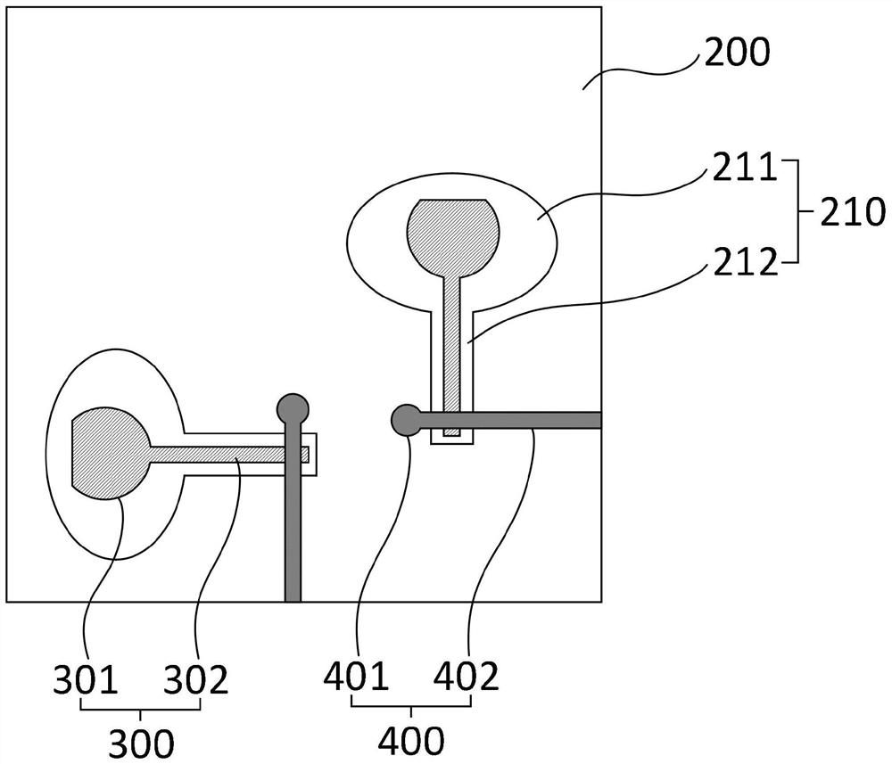
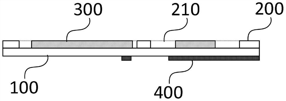
The invention provides an MIMO antenna and mobile communication equipment. The MIMO antenna comprises a dielectric plate, a grounding plate, at least two monopole antennas and microstrip feeder lines,wherein the grounding plate and the monopole antennas are arranged on the front surface of the dielectric plate; the microstrip feeder lines are consistent with the monopole antennas in number and are arranged on the back surface of the dielectric plate; and the grounding plate is provided with slits with the same number as the monopole antennas, the monopole antennas are arranged in the slits ina one-to-one correspondence manner, projections of the microstrip feeder lines and the monopole antennas on the dielectric plate are intersected, and the slits, the monopole antennas and the microstrip feeder lines form an antenna group. The slot antenna is formed by forming the slot in the grounding plate, the monopole antenna is arranged in the slot, and the isolation degree between the antennagroups is increased while the radiation performance of the antenna is ensured by utilizing an antenna orthogonal mode and a polarization diversity principle; in addition, the microstrip feeder line is arranged to feed the monopole antenna, so that the radiation performance of the antenna is improved. The problem of how to realize a high-isolation multi-antenna system in a small space is solved.

Description

Technical field[0001]The present invention relates to the field of antenna technology, in particular to a MIMO antenna and mobile communication equipment.Background technique[0002]The development of the mobile communication market puts forward higher and higher requirements for terminal products. With the increasing number of functional modules, the performance requirements of the antenna have been challenged. Therefore, the performance of the antenna must be further improved in a limited space environment. For this reason, researchers have developed MIMO (Multiple Input Multiple Output) antenna technology. MIMO antenna can effectively improve the performance of the antenna, but the structure of the MIMO antenna itself leads to a large number of antennas.[0003]With the increase of functional modules, the space environment left for antennas becomes smaller and smaller. Therefore, it becomes very important to carry out research on coupling suppression of multi-antenna systems. Most of...

Claims


Application Information

Patent Timeline
IPC IPC(8): H01Q1/48H01Q1/50H01Q1/38H01Q1/52H01Q9/30H01Q21/00
CPCH01Q1/38H01Q1/48H01Q1/50H01Q1/521H01Q9/30H01Q21/0075
Inventor 袁涛
Owner 昆山亿趣信息技术研究院有限公司
Why Eureka
Try Eureka