Wiring terminal contact pin press-fitting device and method

A technology of terminal and press-fitting device, which is applied in the direction of connection, circuit/collector parts, electrical components, etc., can solve the inaccurate distance of the downward movement of the pin row, reduce the quality of pin press-fitting, and affect the pin problems such as the accuracy of material selection to achieve the effect of ensuring accuracy

Inactive Publication Date: 2021-01-01
董存清
View PDF1 Cites 6 Cited by
  • Summary
  • Abstract
  • Description
  • Claims
  • Application Information

AI Technical Summary

Problems solved by technology

[0004] The prior art has the following deficiencies: 1. When pulling the pins, use the pin push rod to push the pin rows in the material slider down by a pin distance, and then the press-fitting mechanism will push out the pins. A single pin is received to complete the pin material removal process; and when the pin push rod pushes the pin row downward, it will provide a downward thrust to the pin row; when the pin row is pushed out by the pin push rod for a After the distance of the pins, the pin row will move down a certain distance due to inertia; and the lower end of the slider is an open structure in order to ensure the smooth sliding of the pin row, and there is no limit effect on the lower end of the pin row, so that The distance of the downward movement of the pin row is inaccurate, which affects the accuracy of the pin insertion
2. When press-fitting the pin and the card holder, the air claw hand in the moving mechanism first clamps the single pin from above and moves it to the corresponding hole of the c

Method used


Image

  • Wiring terminal contact pin press-fitting device and method
  • Wiring terminal contact pin press-fitting device and method
  • Wiring terminal contact pin press-fitting device and method

Examples


Embodiment 1

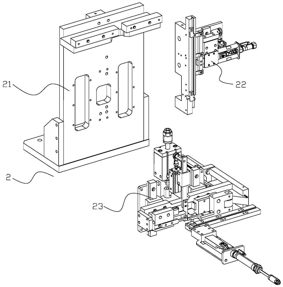
[0033] Such as figure 1 The shown pin press-fitting device 2 includes a press-fit base plate 21 and a pin-pushing mechanism 22 and a pin-pressing mechanism 23 fixed on the press-fit base plate 21; The outlet of the material bending device is connected, and the output end of the pin pushing mechanism 22 is connected with the input end of the pin pressing mechanism 23; the output end of the pin pressing mechanism 23 is connected with the feeding port of the blanking device; The feeding mechanism 22 is used to move the pins connected side by side to move down; the pin depressing mechanism 23 is used to press down a single pin into the corresponding hole of the cartridge.

[0034] The product flow direction of the connection terminal is: the pin pushing mechanism 22 to the pin pressing mechanism 23 .

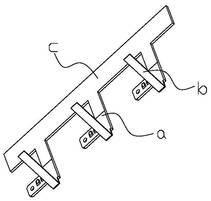
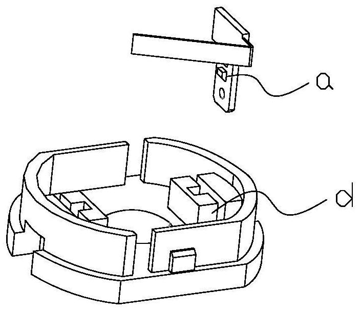
[0035] Such as figure 2 , image 3 Shown is a schematic diagram of the structure of terminal blocks. The terminal block is composed of a pin a and a card seat d: a single pin a...


PUM


Abstract

The invention relates to the field of wiring terminals, in particular to a wiring terminal contact pin press fitting device and method. The device comprises a press-fitting bottom plate, and a contactpin poking mechanism and a contact pin pressing mechanism which are fixed on the press-fitting bottom plate, the input end of the pin poking mechanism is connected with a discharging port of the feeding bending device, and the output end of the pin poking mechanism is connected with the input end of the pin pressing mechanism. The output end of the contact pin pressing mechanism is connected witha feeding port of the discharging device. The contact pin shifting mechanism is used for shifting the contact pins connected side by side to move downwards; the contact pin pressing mechanism is usedfor pressing a single contact pin into a corresponding hole site of the clamping seat. According to the device, by arranging the contact pin poking mechanism, it is guaranteed that the downward movement distance of the contact pin row is accurate, and the contact pin poking accuracy is improved; by arranging the contact pin pressing mechanism, the contact pins are prevented from deviating relative to the hole sites of the clamping base, and the press-fitting quality of the contact pins pressed into the corresponding hole sites of the clamping base is guaranteed.

Description

technical field [0001] The invention relates to the field of connection terminals, in particular to a device and method for pressing pins of connection terminals. Background technique [0002] Terminal block is an accessory product used to realize electrical connection, which is industrially divided into the category of connectors. With the increasing degree of industrial automation and stricter and more precise industrial control requirements, the amount of terminal blocks is gradually increasing. With the development of the electronics industry, the use of terminal blocks is increasing, and there are more and more types. In addition to PCB board terminals, the most widely used ones are hardware terminals, nut terminals, spring terminals and so on. During the working process of the terminal, the outer end of the pin passes through the card seat to connect with the external electrical components, and the internal shrapnel of the pin is connected to its own circuit system, ...

Claims


Application Information

Patent Timeline
IPC IPC(8): H01R43/048H01R43/055
CPCH01R43/048H01R43/055
Inventor 董存清张玉渠
Owner 董存清
Why Eureka
Try Eureka