A driver, an electronic device and a control method for the driver

A control method and a driver technology, which are applied to structural parts of electrical equipment, structural connections of printed circuits, printed circuits connected with non-printed electrical components, etc., can solve problems affecting the working efficiency of driver electronic components and the normal operation of PCB boards. , Reduced working efficiency of components and other issues, to achieve the effect of reducing mutual influence, realizing self-balancing, and improving work efficiency

Active Publication Date: 2021-08-17
GREE ELECTRIC APPLIANCES INC
View PDF4 Cites 0 Cited by
  • Summary
  • Abstract
  • Description
  • Claims
  • Application Information

AI Technical Summary

Problems solved by technology

[0002] Different electronic components have a rated operating temperature, that is, the rated temperature. Electronic devices operating within the rated temperature range have the best working efficiency, and the service life will be extended accordingly. When the electronic components are often subject to excessive self-heating Or the lower ambient temperature will affect the normal operation of the entire PCB board, that is, when the operating temperature of the electronic components is lower or higher than the rated temperature range, the working efficiency between the components will be reduced accordingly
[0003] The drivers in the prior art are mostly used in the normal temperature environment, and the electronic components often face the working state of excessive self-heating, and the prior art only proposes a solution for this research on the heat dissipation between the electronic components, but this driver Although the electronic components on the circuit board are at a lower ambient temperature, although it is good for heat dissipation, when the operating temperature of some electronic components is lower than the rated temperature, the existing driver cannot be adjusted and controlled, which will also affect the working efficiency of the electronic components of the driver.

Method used


Image

  • A driver, an electronic device and a control method for the driver
  • A driver, an electronic device and a control method for the driver
  • A driver, an electronic device and a control method for the driver

Examples


Embodiment Construction

[0038] In order to make the purposes, technical solutions and advantages of the embodiments of the present application clearer, the technical solutions in the embodiments of the present application will be clearly and completely described below in conjunction with the drawings in the embodiments of the present application. Obviously, the described embodiments It is a part of the embodiments of this application, but not all of them. Based on the embodiments in the present application, all other embodiments obtained by persons of ordinary skill in the art without making creative efforts belong to the protection scope of the present application.

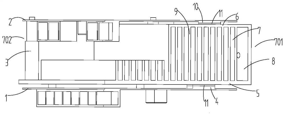
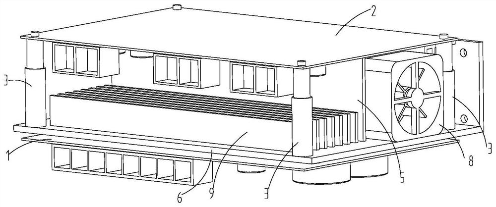
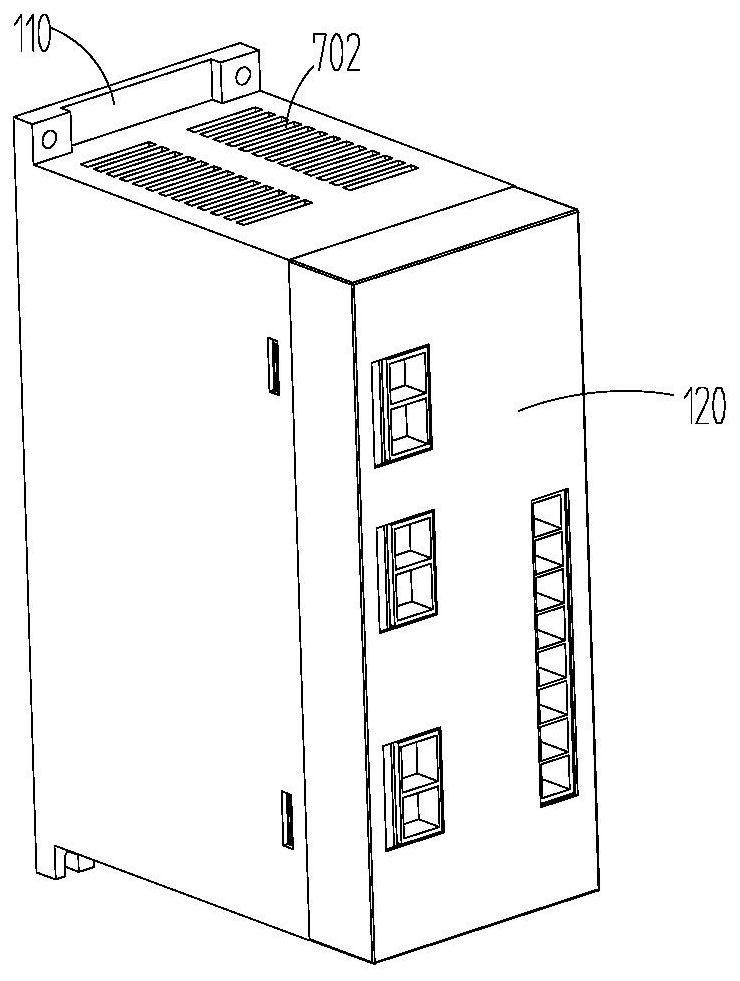
[0039] The electronic components in the driver all have a rated temperature range to achieve higher working efficiency, but the control of the electronic components of the driver in the prior art is basically based on the problem of excessive operating temperature of the electronic components, and the control of the driver is adjusted to...


PUM


Abstract

It relates to the technical field of heat conduction between driver components, and the present application discloses a driver, electronic equipment, and a control method for the driver. It includes a first substrate and a second substrate. The first basic substrate and the second substrate are used to install electronic components. It also includes an adjustment piece. The adjustment piece is connected to the first substrate and the second substrate at intervals. The two ends of the adjustment piece are respectively connected to the first substrate and The second substrate, the adjusting member can change the distance between the first substrate and the second substrate by stretching or shrinking. Compared with the prior art, the distance between the first substrate and the second substrate can be changed through the elongation or contraction of the adjustment member, thereby changing the heat conduction efficiency between the first substrate and the second substrate. In a low temperature environment, The working temperature between different electronic components can be adjusted by using the waste heat of the electronic components in the driver, so as to effectively improve the working efficiency of the electronic equipment and prolong the service life of the electronic equipment.

Description

technical field [0001] The present application relates to the technical field of heat conduction between driver components, and in particular, relates to a driver, an electronic device, and a control method for the driver. Background technique [0002] Different electronic components have a rated operating temperature, that is, the rated temperature. Electronic devices operating within the rated temperature range have the best working efficiency, and the service life will be extended accordingly. When the electronic components are often subject to excessive self-heating Or the lower ambient temperature will affect the normal operation of the entire PCB board, that is, when the operating temperature of the electronic components is lower than or higher than the rated temperature range, the working efficiency between the components will be reduced accordingly. [0003] The drivers in the prior art are mostly used in the normal temperature environment, and the electronic compone...

Claims


Application Information

Patent Timeline
Patent Type & Authority Patents(China)
IPC IPC(8): H05K1/14H05K1/18H05K7/20
CPCH05K1/144H05K1/18H05K7/20136H05K7/205
Inventor 邵帅崔迪叶俊奇
Owner GREE ELECTRIC APPLIANCES INC
Why Eureka
Try Eureka