Quick locking device for water cup

A locking device and fast technology, applied to drinking water containers, etc., can solve the problems of water bottles that are not easy to twist, unsanitary, and the bottle mouth and mouth do not fit together, and achieve the effects of convenient operation, long service life and simple structure

Pending Publication Date: 2021-01-05
航天科工哈尔滨风华有限公司
View PDF0 Cites 0 Cited by
  • Summary
  • Abstract
  • Description
  • Claims
  • Application Information

AI Technical Summary

Problems solved by technology

[0010] The present invention solves the problems that the current existing cups and bottles are not easy to twist, the mouth of the bottle and the mouth do not fit together, and are unhygienic. Aiming at the deficiencies of the prior art, the present invention discloses a "quick locking device for water cups"

Method used


Image

  • Quick locking device for water cup
  • Quick locking device for water cup
  • Quick locking device for water cup

Examples


specific Embodiment approach 1

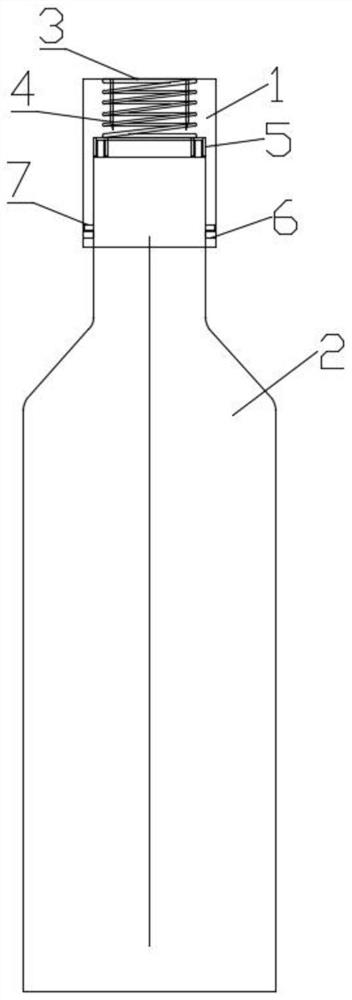
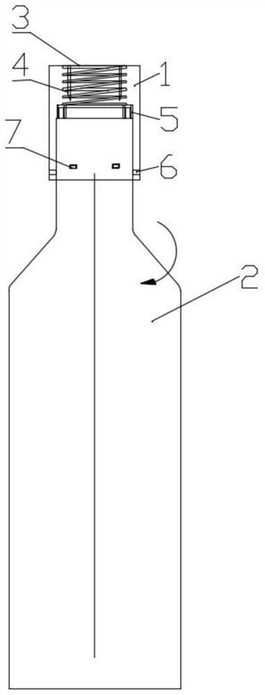
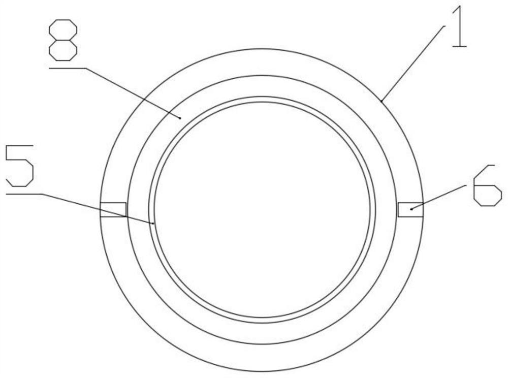
[0035] Specific implementation mode one: combine Figure 1-Figure 4 Describe this embodiment, the water cup fast locking device of this embodiment comprises bottle cap 1 and bottle body 2, and bottle cap 1 is installed on the bottle body 2, and described bottle cap 1 comprises spring 3, cup mouth presser 5 and Bottle cap limit block 6, one end of spring 3 is fixedly installed on the bottom of bottle cap 1, specifically, one end of spring 3 is fixedly installed on the inner bottom of bottle cap 1, and the cup holder 5 is fixedly installed on the other end of spring 3 , the inner wall of the bottle cap 1 is fixedly installed with a bottle cap limit block 6, and the bottle body 2 is equipped with a bottle body limit block 7 that is compatible with the bottle cap limit block 6, and the bottle body limit block 7 is fixedly installed At the bottle mouth of the bottle body 2, when the bottle cap 1 is knocked on the bottle body 2, the bottle cap 1 is first put on the bottle body 2, an...

specific Embodiment approach 2

[0036] Specific implementation mode two: combination Figure 1-Figure 2 , Figure 4 Describe this embodiment, the water cup fast locking device of this embodiment, there is a spring guide 4 inside the spring 3, one end of the spring guide 4 is fixedly installed on the bottom of the bottle cap 1, the outer wall of the spring guide 4 is connected with the spring 3 Inner wall contact, because the size of the spring 3 is smaller than the inner diameter of the bottle cap 1, the spring 3 is prone to deflection when compressed inside the bottle cap 1, after the spring guide 4 is installed, the spring guide 4 is in contact with the inner ring of the spring 3 , to play the role of supporting the spring 3, avoiding the spring 3 from shifting when it is pressed down.

specific Embodiment approach 3

[0037] Specific implementation mode three: combination Figure 1-Figure 2 , Figure 4 Describe this embodiment, the water cup quick locking device of this embodiment, the spring 3 is a cylindrical helical spring, the cylindrical helical spring is relatively common, the cost is low and the elasticity is moderate, and the spring 3 can be replaced at any time when it is damaged.


PUM

PropertyMeasurementUnit
Thicknessaaaaaaaaaa
Thicknessaaaaaaaaaa

Abstract

The invention discloses a quick locking device for water cup and belongs to the field of cups. The problems that existing cups are not easy to screw, a opening and a mouth are not attached to each other, and the existing cups are is not sanitary are solved. The comprises a cap and a body, the cap is installed on the body, the cap comprises a spring, a cup opening pressing device and a cap limitingblock, one end of the spring is fixedly installed at the bottom of the cap, the cup opening pressing device is fixedly installed at the other end of the spring, and the cap limiting block is fixedlyinstalled on the inner wall of the cap; a body limiting block matched with the cap limiting block is installed on the body, and the body limiting block is fixedly installed at a opening of the body. The rapid cup locking device is clean and sanitary, the cap can be opened only by slightly screwing the cap by a certain angle, people with small strength can open the cap, and the rapid cup locking device is simple in structure, convenient to operate, durable and free of thread slipping.

Description

technical field [0001] The invention relates to a fast locking device for water cups, which belongs to the field of water cups. Background technique [0002] Water cups are also called water bottles. Water cups are usually containers for people to hold liquids. They can be used to drink tea, water, and beverages at ordinary times. A water cup is a container used to carry liquids in most cases, usually made of plastic, glass, ceramics or stainless steel, and paper cups or plastic cups are often used to pack drinks in restaurants. The cups are mostly cylindrical, open on the top, and hollow for holding things. Cups for hot drinks have handles for convenience and practicality. Due to the opening of the cup, the liquid in the cup is easily polluted by the surrounding dust, so when it is left for a long time, cover it with a cup cover; [0003] At present, most of the installations of water bottles and bottle caps on the market adopt two methods, one is the up and down snap-on...

Claims


Application Information

Patent Timeline
IPC IPC(8): A47G19/22
CPCA47G19/22A47G19/2205
Inventor 吕博关博文王立超沈聪解子豪常传东孟昭阳范恒
Owner 航天科工哈尔滨风华有限公司
Why Eureka
Try Eureka