Automatic locking device for core roller of ring rolling machine

An automatic locking, core roll technology, applied in metal rolling and other directions, can solve the problems of shortening the core roll installation time, core roll falling off, bolt loosening, etc., to save physical strength and time, improve firmness, and avoid core rolls shedding effect

Active Publication Date: 2021-01-05
ZHUCHENG SHENGYANG MACHINERY
View PDF7 Cites 1 Cited by
  • Summary
  • Abstract
  • Description
  • Claims
  • Application Information

AI Technical Summary

Problems solved by technology

[0003] In order to solve the above technical problems, the present invention provides an automatic locking and fixing of the core roller, which can effectively save physical strength and time when fastening with bolts, simplify the locking method of the core roller, shorten the installation time of the core roller, and facilitate the core alignment. Rollers can be quickly disassembled to improve work efficiency. At the same time, the firmness of the core roll is improved to avoid loosening of the bolts when the bolts are tightened and cause the core roll to fall off. This improves the safety of the equipment and improves the practicality and reliability of ring rolling. Core roll automatic locking device

Method used


Image

  • Automatic locking device for core roller of ring rolling machine
  • Automatic locking device for core roller of ring rolling machine
  • Automatic locking device for core roller of ring rolling machine

Examples


Embodiment Construction

[0018] The specific implementation manners of the present invention will be further described in detail below in conjunction with the accompanying drawings and embodiments. The following examples are used to illustrate the present invention, but are not intended to limit the scope of the present invention.

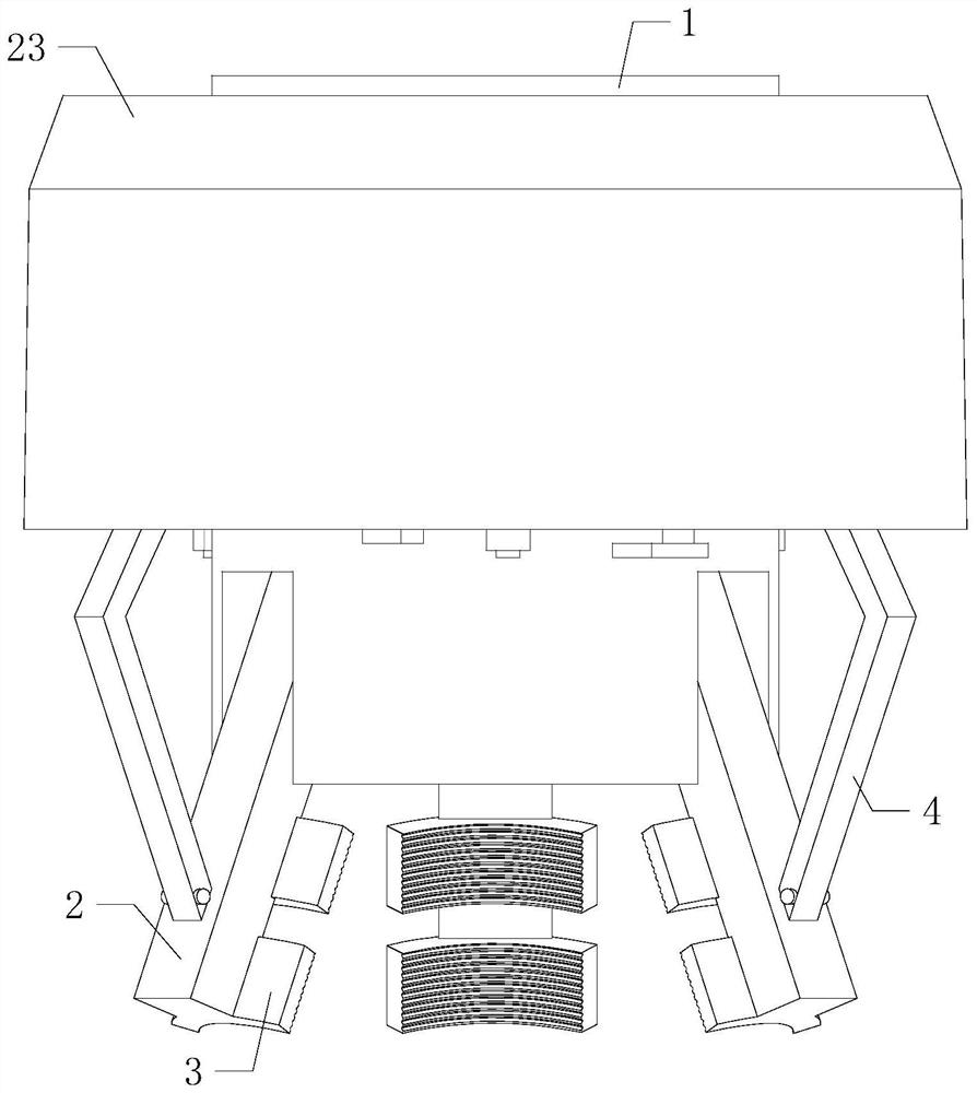
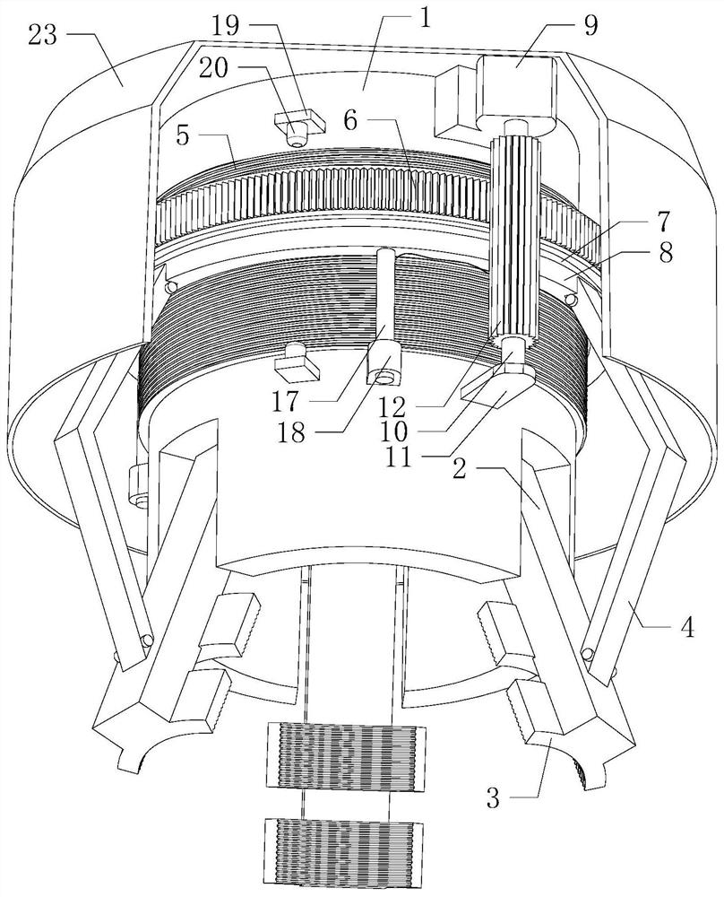
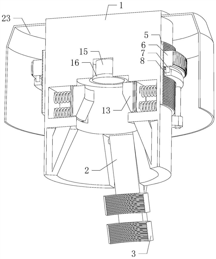
[0019] Such as Figure 1 to Figure 4 As shown, an automatic locking device for ring rolling mandrel rolls of the present invention inserts the top of the external core roll into the jack when it is working, and the tapered surface on the lower side of the inner wall of the jack can easily guide the core roll. The top of the core roller is in contact with the top of the inner wall of the socket, and two sets of motors 9 are turned on. The two sets of motors 9 respectively drive two sets of long gears 12 to rotate through two sets of rotating shafts 10. Both sets of long gears 12 mesh with the internal thread ring 6. The long gear 12 drives the inner threaded ring 6 to rota...


PUM


Abstract

The invention relates to the technical field of mechanical equipment, in particular to an automatic locking device for a core roller of a ring rolling machine. Through automatically locking and fixingthe core roller, the physical strength and the time spent when a bolt is adopted for fastening can be effectively saved, the locking mode of the core roller is simplified, the installation time of the core roller is shortened, quick disassembly and assembly of the core roller are facilitated, the working efficiency is improved, meanwhile, the firmness of the core roller is improved, the occurrence of the phenomenon that the core roller falls off due to the fact that the bolt is loosened when the bolt is fastened is avoided, the safety of the equipment is improved, and practicability and reliability are improved. The automatic locking device for the core roller of the ring rolling machine comprises a fixing column, three sets of first push plates and three sets of second push plates, wherein the top of the fixing column is installed on an external ring rolling machine; an inserting hole is formed in the middle of the bottom end of the fixing column in a communicating mode; the lower side of the inner wall of the inserting hole is a conical surface; three sets of installing grooves are annularly and evenly formed in the lower side of the outer wall of the fixing column in a communicating mode; the inner sides of the three sets of installation grooves communicate with the inner part of the inserting hole; and the upper sides of the three sets of first push plates are respectivelypositioned in the three sets of installation grooves.

Description

technical field [0001] The invention relates to the technical field of mechanical equipment, in particular to an automatic locking device for ring rolling core rolls. Background technique [0002] As we all know, the ring rolling machine is mainly to squeeze the ring-shaped workpiece and make it plastically deformed, so as to obtain the product of the required specification. The core roller on the ring rolling machine is mainly to position and squeeze the workpiece. The existing core roll During assembly, multiple sets of bolts are usually used for fastening. However, when this method is used, the fastening method of the core roll is more cumbersome, the physical strength of the workers is greater, the time required for fastening is longer, the work efficiency is low, and it is not easy to fix The core roll is replaced quickly, and the core roll is fastened by bolts, which has poor firmness, and the bolts are prone to loosening and the core roll falls off when the time comes...

Claims


Application Information

Patent Timeline
Patent Type & Authority Applications(China)
IPC IPC(8): B21H1/06
CPCB21H1/06
Inventor 蔡利川侯文杰梁夕杰张春彦曹康
Owner ZHUCHENG SHENGYANG MACHINERY
Why Eureka
Try Eureka