
Clamping device

A clamping device and clamping arm technology, applied in the direction of chuck, manipulator, cable laying equipment, etc., can solve the problem of inability to design a clamping device

Inactive Publication Date: 2021-01-05
WUHAN MARINE MACHINERY PLANT
View PDF6 Cites 2 Cited by
  • Summary
  • Abstract
  • Description
  • Claims
  • Application Information

AI Technical Summary

Problems solved by technology

[0004] However, since the shapes of the objects to be clamped are different in each cable laying construction, there will be a large number of idle clamping devices after each cable laying construction is completed.
Moreover, during the cable laying construction process, there are still some objects with irregular shapes that cannot be designed with corresponding clamping devices. Therefore, designing a clamping device with high versatility can reduce construction costs and improve construction efficiency.

Method used


Image

  • Clamping device
  • Clamping device
  • Clamping device

Examples


Embodiment Construction

[0026] In order to make the purpose, technical solution and advantages of the present disclosure clearer, the implementation manners of the present disclosure will be further described in detail below in conjunction with the accompanying drawings.

[0027] Unless otherwise defined, the technical terms or scientific terms used herein shall have the usual meanings understood by those having ordinary skill in the art to which the present disclosure belongs. "First", "second", "third" and similar words used in the specification and claims of this disclosure do not indicate any order, quantity or importance, but are only used to distinguish different components . Likewise, words like "a" or "one" do not denote a limitation in quantity, but indicate that there is at least one. Words such as "comprises" or "comprising" and similar terms mean that the elements or items listed before "comprising" or "comprising" include the elements or items listed after "comprising" or "comprising" a...


PUM


Abstract

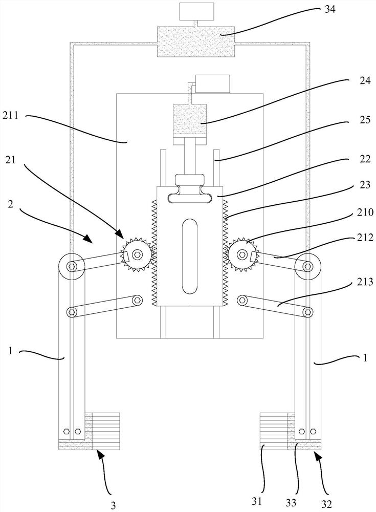
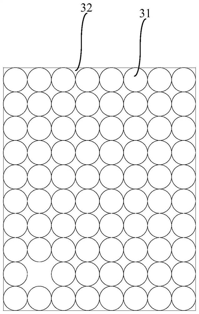
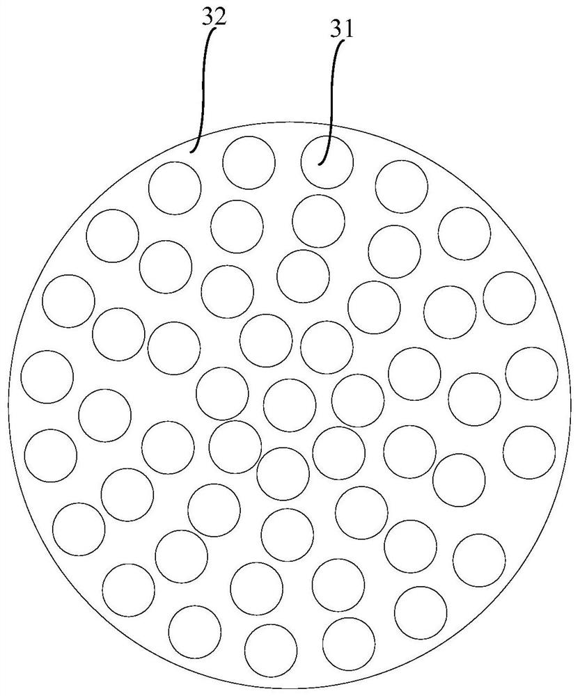
The invention provides a clamping device. The clamping device comprises: two clamping arms which are oppositely arranged; a drive unit, which is configured to drive the two clamping arms to get closeto each other or get away from each other; two clamping units, which are located on the opposite side faces of the two clamping arms respectively, wherein each clamping unit comprises a control pieceand a plurality of supporting rods arranged in an array mode, and the axial direction of each supporting rod is parallel to the moving direction of the two corresponding clamping arms, and the controlpiece is configured to drive all the supporting rods in the clamping unit to move in the axial direction of the supporting rods. The clamping device can be suitable for clamping objects of differentappearance structures and can be repeatedly used in a cable laying construction process, so that construction cost is reduced.

Description

technical field [0001] The present disclosure relates to the technical field of cable laying, in particular to a clamping device. Background technique [0002] Cable laying refers to the process of laying and installing cables to form cable routes. During the cable laying construction process, the cables need to be placed neatly, and the relative positions between the cables need to be clamped by clamps. For example, in the laying construction process, in order to reduce the inductance of the line, the cables are required to be laid in a zigzag shape, so it is necessary to use corresponding clamps to clamp multiple cables together to form a zigzag shape. Moreover, during the construction process of laying, it is usually necessary to clamp objects of various shapes and structures. Therefore, the clamping device is an important equipment in the cable laying construction. [0003] In the related art, different clamping devices are usually designed according to the shape of o...

Claims


Application Information

Patent Timeline
IPC IPC(8): B25J15/02B25J15/00H02G1/06
CPCB25J15/0028B25J15/0033B25J15/026H02G1/06
Inventor 曾庆威李相远李海马平安
Owner WUHAN MARINE MACHINERY PLANT
Learn More