3D printing head made of continuous fiber reinforced material and using method

A technology of fiber-reinforced materials and reinforced materials, which is applied in the direction of additive processing, 3D object support structures, coating devices, etc., can solve the problems of limiting the speed of 3D printing of continuous fiber composite materials, large moving structures, etc., to prevent nozzles from The effect of flow phenomenon, eliminating the pressing mechanism, and increasing the printing speed

Active Publication Date: 2021-01-05
GUANGZHOU ELECTRONICS TECH
View PDF16 Cites 2 Cited by
  • Summary
  • Abstract
  • Description
  • Claims
  • Application Information

AI Technical Summary

Problems solved by technology

[0004] However, the current research on the 3D printing process of continuous fiber reinforced composite materials is still in its infancy, and there are still some technical difficulties. To realize it with a device, not only the motion structure is huge, but also complex motion control algorithms are required, which greatly limits the molding speed of continuous fiber composite 3D printing

Method used


Image

  • 3D printing head made of continuous fiber reinforced material and using method
  • 3D printing head made of continuous fiber reinforced material and using method
  • 3D printing head made of continuous fiber reinforced material and using method

Examples


Embodiment

[0035]It is to be understood that the terms "center", "longitudinal", "transverse", "length", "width", "thickness", "upper", "lower", "front", "rear", "left", "Right", "Vertical", "Horizontal", "Top", "Bottom", "Inner", "Outer", "Clockwise", "Counterclockwise", "Axial", "Radial", " The orientation or positional relationship indicated by "circumferential direction" is based on the orientation or positional relationship shown in the drawings, and is only for the convenience of describing the present invention and simplifying the description, rather than indicating or implying that the referred device or element must have a specific orientation, Constructed and operative in a particular orientation and therefore are not to be construed as limitations of the invention.

[0036] In addition, the terms "first" and "second" are used for descriptive purposes only, and cannot be interpreted as indicating or implying relative importance or implicitly specifying the quantity of indicated...


PUM


Abstract

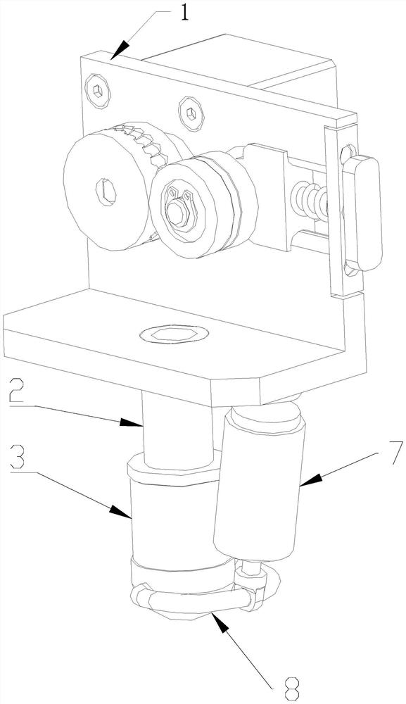
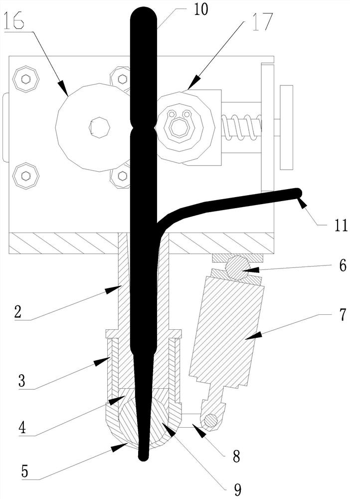
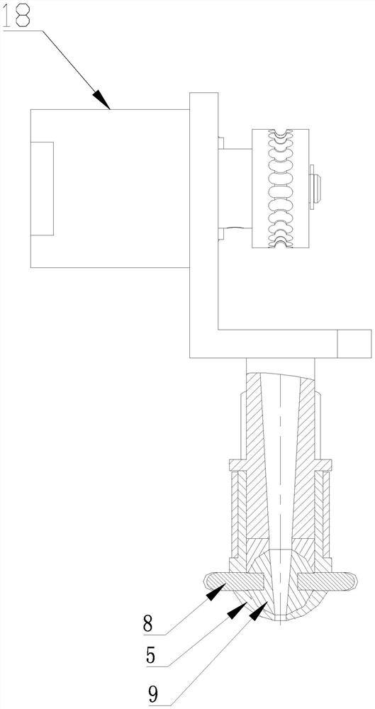
The invention discloses a 3D printing head made of a continuous fiber reinforced material and a using method, and relates to the technical field of fused deposition. The 3D printing head comprises a base frame, and a feeding mechanism, a printing nozzle and a shearing mechanism arranged on the base frame, wherein the printing nozzle comprises a throat pipe, a heating pipe and a nozzle, the throatpipe is provided with a first cavity in the length direction, the nozzle is connected to the lower end of the throat pipe, the heating pipe is arranged on the outer wall of the throat pipe and the outer wall of the nozzle in a sleeving manner, and the first cavity communicates to a nozzle discharging port of the nozzle; the shearing mechanism comprises a power piece and a swing ball, the swing ball is arranged between the first cavity and the nozzle discharging port and is provided with a second cavity communicating to the first cavity, one end of the power piece is connected to the swing ball, and the other end of the power piece is connected to the base frame; and the power piece is used for driving the swing ball to rotate at a certain angle, so that the swing ball is switched between afirst working state and a second working state.

Description

technical field [0001] The invention relates to the field of fused deposition technology, in particular to a 3D printing head for continuous fiber reinforced materials and a method for using it Background technique [0002] Continuous fiber composites have excellent properties such as high modulus, high strength, low specific gravity, and wear resistance, and have important application prospects in aerospace, national defense and military industries, and civil industries. Traditional continuous fiber composite molding processes include thermocompression molding, RTM molding, winding molding, pultrusion molding, lamination molding, etc., which have played a very important role in promoting the development and application of continuous fiber composite materials, but there have always been some The disadvantages cannot be overcome. For example, most molding processes require special molds. The molding process is complicated and the processing cost is high. It is difficult to ac...

Claims


Application Information

Patent Timeline
Patent Type & Authority Applications(China)
IPC IPC(8): B29C64/209B29C64/118B29C64/321B33Y30/00B33Y40/00
CPCB33Y30/00B33Y40/00B29C64/118B29C64/209B29C64/321
Inventor 杜俊斌张海强赵建华陈晓佳
Owner GUANGZHOU ELECTRONICS TECH
Why Eureka
Try Eureka