Novel paper binding machine

A binding machine and paper technology, applied in binding and other directions, can solve problems such as poor pressing, inconvenient maintenance, and difficult disassembly and assembly, and achieve the effects of simple structure, easy protection, and convenient operation

Inactive Publication Date: 2021-01-05
YIWU UPRIGHT STATIONERY
View PDF0 Cites 0 Cited by
  • Summary
  • Abstract
  • Description
  • Claims
  • Application Information

AI Technical Summary

Problems solved by technology

[0003] Existing paper binding machines have certain disadvantages when in use. First, the punching head is flush when binding, and the pressure is relatively high, which cannot be pressed well, which is not conducive to people's use. In addition, It is difficult to carry out the binding operation when using it, it is difficult to disassemble and assemble, and it is inconvenient to overhaul, which brings certain adverse effects to people's use process. Therefore, we propose a new type of paper binding machine

Method used


Image

  • Novel paper binding machine
  • Novel paper binding machine
  • Novel paper binding machine

Examples


Embodiment 1

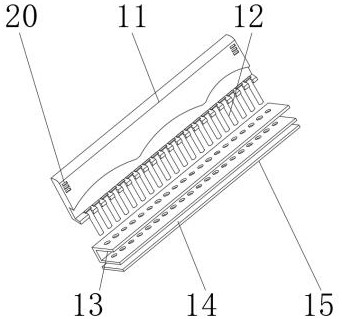
[0026] Embodiment one, such as figure 2 and 3 As shown, the position of the lower end of the arched pressing plate 11 is a combination of multiple groups of arched structures, and the interior is wavy. A positioning groove is provided between the T-shaped punching needle 12 and the positioning support 13, and the outer wall of the T-shaped punching needle 12 is positioned by positioning. The slot is movably connected to the inner side of the positioning support 13. The inside of the positioning support 13 is a hollow structure. A chute and a return spring are arranged between the arched pressing plate 11 and the fixed side plate 16. Both sides of the arched pressing plate 11 pass through the chute. 1. The return spring is movably connected to the inner side of the fixed side plate 16, which facilitates better paper stamping and binding operations, reduces pressure, makes the operation more convenient and practical, and can also facilitate and better position and increase the ...

Embodiment 2

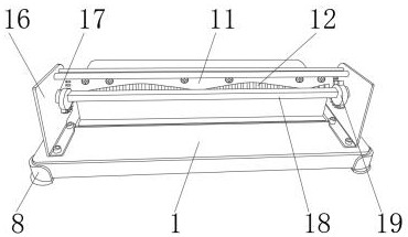
[0027] Embodiment two, such as Figure 4 As shown, the outer two ends of the fixed side plate 16 are provided with a dismounting block 7, between the fixed side plate 16 and the dismounting block 7, an adjusting frame 4 is arranged, and the inner side of the upper end of the adjusting frame 4 is provided with a remote lever 5, and the remote lever 5 Positioning pins 3 are arranged at both ends of the two sides, a bearing is arranged between the fixed side plate 16 and the rotating shaft 17, the inner wall of the fixed side plate 16 is movably connected with the outer wall of the rotating shaft 17 through the bearing, and between the rotating shaft 17 and the pressing gear 19 A fixed block is provided, and one end of the rotating shaft 17 is fixedly connected with the interior of the press-fitting gear 19 through the fixed block. A block is arranged between the adjusting frame 4 and the rotating shaft 17. The outer wall is fixedly connected, and the lower end of the adjustment ...

Embodiment 3

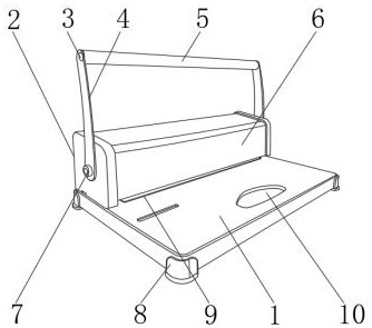
[0028] Embodiment three, such as figure 1 As shown, a positioning block is arranged between the side shell 2 and the fixed side plate 16, the outside of the fixed side plate 16 is detachably connected to the inside of the side shell 2 through the positioning block, and the side shell 2 and the main body shell 6 A connecting block is provided, and the inner side of the side shell 2 is fixedly connected with both sides of the main body shell 6 through the connecting block. The structure is simple, detachable and easy to repair.


PUM


Abstract

The invention discloses a novel paper binding machine which comprises a device base. A fixed side plate is fixedly connected to the upper end of the device base; antiskid supporting legs are fixedly connected to the periphery of the device base; a rotating shaft is arranged on the inner wall of the fixed side plate; a press-fit gear is fixedly connected to the inner side of the rotating shaft; theinner side of a paper positioning plate is fixedly connected with a supporting rod; the inner side of the fixed side plate is provided with an arch-shaped pressing plate and a containing plate; and the lower end of the arch-shaped pressing plate is provided with a T-shaped stamping needle. The novel paper binding machine provided by the invention is provided with the arch-shaped pressing plate, apositioning support and a detachable shell, so that paper stamping and binding operation can be conveniently and better carried out, pressure is reduced, operation is conducted more conveniently, practicability is achieved, positioning can be conveniently and better carried out, the press-fit stability is improved, a binding effect is more excellent, the structure is simple, maintenance is more conveniently conducted, materials are saved, and better use prospects are brought.

Description

technical field [0001] The invention relates to the field of office supplies, in particular to a novel paper binding machine. Background technique [0002] The paper binding machine is a supporting device for paper binding. It can position the paper mechanically. The operation is simple, the speed is fast, the cost of consumables is low, and the style is exquisite. Fixed, the use types of binding machines are more diverse. Generally, manual office is used, which is low in cost, simple and practical. With the continuous development of science and technology, people have higher and higher requirements for the manufacturing process of paper binding machines. [0003] Existing paper binding machines have certain disadvantages when in use. First, the punching head is flush when binding, and the pressure is relatively high, which cannot be pressed well, which is not conducive to people's use. In addition, The binding operation cannot be performed very conveniently during use, the...

Claims


Application Information

Patent Timeline
IPC IPC(8): B42B5/00
CPCB42B5/00
Inventor 朱堂葵邵陆义
Owner YIWU UPRIGHT STATIONERY
Why Eureka
Try Eureka