Repeating unmanned aerial vehicle electromagnetic catapult system and unmanned aerial vehicle hangar

An unmanned aerial vehicle, machine electromagnetic technology, applied in the direction of launch/drag transmission, collector, electric vehicle, etc., can solve the problems of heavy workload of safety guarantee, troublesome control and operation, and high requirements of operators, so as to improve the ejection efficiency , easy maintenance, convenient and flexible transportation

Pending Publication Date: 2021-01-05
NAT UNIV OF DEFENSE TECH
View PDF0 Cites 4 Cited by
  • Summary
  • Abstract
  • Description
  • Claims
  • Application Information

AI Technical Summary

Problems solved by technology

[0003] The current situation is that UAVs not exceeding 50kg use rubber band ejection, UAVs of about 100kg use pneumatic ejection, those not exceeding 500kg mostly use hydraulic / pneumatic ejection, and those less than 2000kg use rocket boosting. There are disadvantages of troublesome control and operation, and higher requirements for operators
Moreover, the speed of these launch methods is difficult to control, and there are fewer types of drones that can be used for each launch method
In addition, the rocket boosting method involves the use of gunpowder, so the workload for safety and security is huge
Furthermore, there are still disadvantages such as large equipment volume, poor mobility, and high energy consumption, which affect the battlefield situation.

Method used


Image

  • Repeating unmanned aerial vehicle electromagnetic catapult system and unmanned aerial vehicle hangar
  • Repeating unmanned aerial vehicle electromagnetic catapult system and unmanned aerial vehicle hangar
  • Repeating unmanned aerial vehicle electromagnetic catapult system and unmanned aerial vehicle hangar

Examples


Embodiment Construction

[0030] In order to make the technical solutions and advantages of the present invention clearer, the present invention will be further described in detail below in conjunction with the accompanying drawings and embodiments. It should be understood that the specific embodiments described here are only used to explain the present invention, not to limit the present invention.

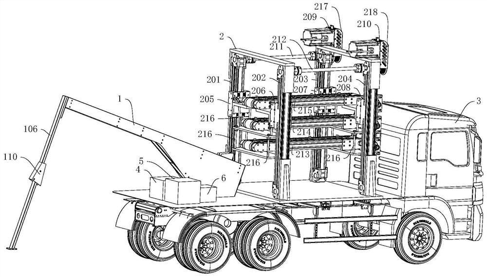
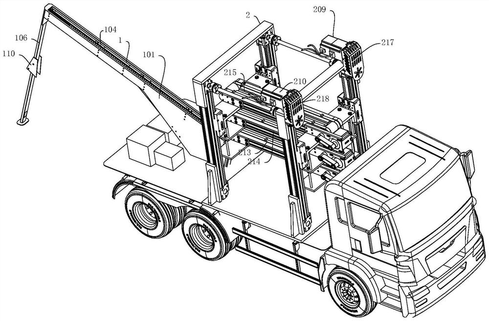
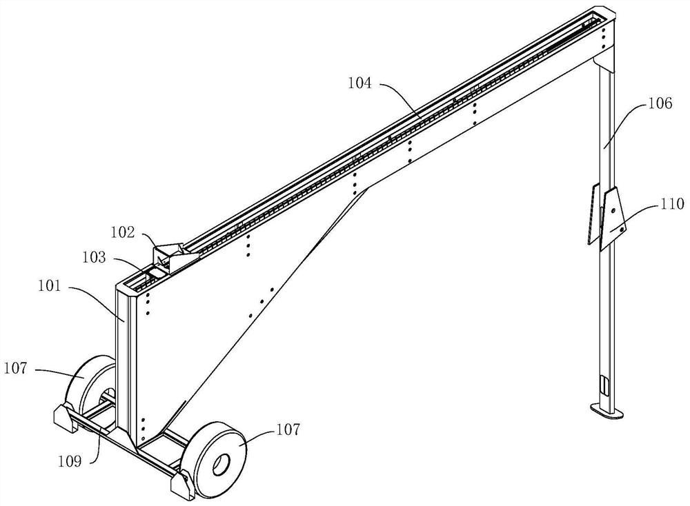
[0031] The present invention provides a continuous UAV electromagnetic ejection system, comprising an UAV electromagnetic ejection device 1, an UAV hangar 2, and both the UAV electromagnetic ejection device 1 and the UAV hangar 2 are mounted on a mobile transportation device 3 (such as a vehicle) on. The mobile transport equipment 3 (such as a vehicle) is also equipped with a control system 4 , an energy storage device 5 and a driver 6 . The UAV electromagnetic ejection device 1 is used as the actuator for UAV ejection to provide the UAV with the acceleration thrust required for ejection and take-off. Th...


PUM


Abstract

The invention discloses a repeating unmanned aerial vehicle electromagnetic catapult system and an unmanned aerial vehicle hangar. The system comprise an unmanned aerial vehicle electromagnetic catapult device and the unmanned aerial vehicle hangar, the unmanned aerial vehicle hangar is arranged on one side of the unmanned aerial vehicle catapulting end of the unmanned aerial vehicle electromagnetic catapult device, the unmanned aerial vehicle hangar comprises a conveying mechanism capable of carrying a certain number of unmanned aerial vehicles, and an unmanned aerial vehicle catapulting platform can be filled with an unmanned aerial vehicle carried by the conveying mechanism; and after the unmanned aerial vehicle catapulting platform carries the unmanned aerial vehicle, the unmanned aerial vehicle catapulting platform is driven by a catapulting motor to move in an accelerated mode along a catapulting guide rail, after catapulting take-off of the unmanned aerial vehicle is achieved, the unmanned aerial vehicle catapulting platform is braked and moves reversely along the catapulting guide rail, and resetting of the unmanned aerial vehicle catapulting platform is achieved to preparenext unmanned aerial vehicle loading and catapulting. The unmanned aerial vehicle hangar realizes unmanned aerial vehicle storage and transportation. At ordinary times, a certain number of unmanned aerial vehicles can be stored, so the maintainability and reliability of the unmanned aerial vehicles are improved; and in wartime, the electromagnetic catapult can be continuously filled with the unmanned aerial vehicles through the conveying mechanism, so continuous catapult-assisted take-off of the unmanned aerial vehicles is achieved.

Description

technical field [0001] The invention belongs to the technical field of ejection and take-off of unmanned aerial vehicles, and in particular relates to an electromagnetic ejection system for continuous unmanned aerial vehicles using an unmanned aerial vehicle hangar. Background technique [0002] With the continuous development of modern warfare, today's military combat methods have undergone tremendous changes. With the emergence of new combat concepts such as cluster operations, coordinated operations, and unmanned operations, UAV clusters have become indispensable military equipment. , it is of great significance to conduct research on UAV swarm technology. The UAV cluster take-off method is a hot issue in the current UAV technology research. Electromagnetic catapult, an emerging UAV take-off method, has obvious advantages compared with the traditional take-off method. [0003] The current situation is that UAVs not exceeding 50kg use rubber band ejection, UAVs of about 1...

Claims


Application Information

Patent Timeline
IPC IPC(8): B64F1/06B60P3/11H02J7/34
CPCB60P3/11B64F1/06H02J7/345
Inventor 吴峻孟庆富王湘谢广磊
Owner NAT UNIV OF DEFENSE TECH
Why Eureka
Try Eureka