Catapult of flywheel-type high-speed unmanned aerial vehicle

A catapult and flywheel-type technology, applied in the field of UAV launching devices, can solve the problems of low launch speed, long acceleration distance, complex and huge system, etc., and achieve less intermediate transfer process, short acceleration distance and high launch speed Effect

Inactive Publication Date: 2016-07-27
BEIJING INSTITUTE OF TECHNOLOGYGY
View PDF8 Cites 18 Cited by
  • Summary
  • Abstract
  • Description
  • Claims
  • Application Information

AI Technical Summary

Problems solved by technology

Rocket boosting uses the booster rocket as the power, and the UAV flies away from the launch device under the thrust of the booster rocket. It has the advantages of mature technology, large thrust range, low cost, poor safety and concealment, and consumable equipment and technical support costs. higher disadvantage
Gas-liquid ejection mainly uses gas-hydraulic energy as the power of UAV ejection, which has the advantages of good safety and concealment, good economy, good adaptability, etc., and has the disadvantages of complex and huge system, difficult technology, difficult transportation, and high cost.
Gas ejection refers to the direct use of gunpowder gas to launch drones, which usually has high anti-overload requirements for drones and poor adjustability
Elastic ejection converts the elastic potential energy of elastic elements (such as rubber bands and springs) into mechanical energy as power to provide the speed required for the drone to take off. It has the advantages of simple structure and light mechanism, but it is only suitable for small drones. , and limited by the characteristics of the elastic element, the use of elastic ejection has problems such as low launch speed, non-uniform change of launch overload, long acceleration distance, etc.
Even if the pulley block is used to accelerate, there is a large amount of energy consumed and the problem of low mechanical efficiency

Method used


Image

  • Catapult of flywheel-type high-speed unmanned aerial vehicle
  • Catapult of flywheel-type high-speed unmanned aerial vehicle
  • Catapult of flywheel-type high-speed unmanned aerial vehicle

Examples


Embodiment Construction

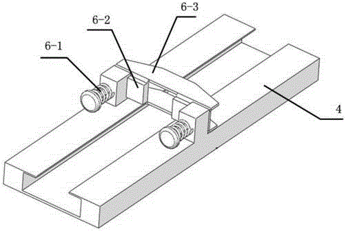
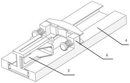
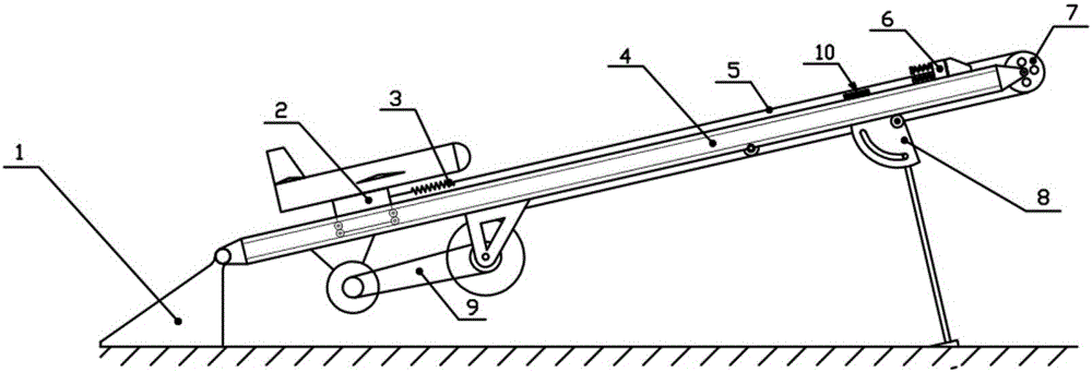
[0017] Referring to the accompanying drawings, a flywheel-type high-speed unmanned aerial vehicle catapult includes: a support seat 1, a tackle 2, a frame body 4, a traction cable 5, a blocking device 6, a guide wheel 7, a bracket 8, a power system 9 and a position sensor 10;

[0018] The support seat 1 and the bracket 8 are used to support the frame body 4, so that the frame body 4 is inclined upward at a set angle;

[0019] The tackle 2 moves on the slideway of the frame body 4, on which a high-speed drone is connected, and the head of the tackle 2 is provided with a buffer spring 3;

[0020] The power system 9 provides traction power to the tackle 2 through the traction cable 5 bypassing the guide wheel 7;

[0021] The position sensor 10 and the blocking device 6 are installed on the frame body 4, and when the position sensor 10 senses that the tackle 2 passes, it sends a stop signal to the power system 9; the blocking device 6 is used to block the movement of the tackle 2...


PUM


Abstract

The invention relates to a launcher of an unmanned aerial vehicle, in particular to a catapult of an unmanned aerial vehicle. According to the technical scheme of the catapult of the flywheel-type high-speed unmanned aerial vehicle, the unmanned aerial vehicle is arranged on a tackle and located at a launching position before being launched, a clutch in a power system is in a disconnected state, a motor drives a flywheel to rotate, and the rotating speed is set according to launching requirements; when the unmanned aerial vehicle is launched, the clutch of the power system is connected, the flywheel drives a winding wheel to rotate, a traction rope is wound into the winding wheel and drives the tackle and the unmanned aerial vehicle to move in an accelerated mode, when the tackle moves to a tackle position sensor, the clutch is controlled to be disconnected, the tackle continues to move forwards and is blocked by a blocking device, the winding wheel stops rotating, and the unmanned aerial vehicle flies out accordingly; after launching is finished, the tackle is pulled back to the initial launching position. According to the catapult of the unmanned aerial vehicle, the flywheel serves as an energy storage element and can rapidly accelerate the unmanned aerial vehicle to a large speed on a very short track, and catapult launching of the unmanned aerial vehicle with a high speed requirement is achieved.

Description

technical field [0001] The invention relates to an unmanned aerial vehicle launching device, in particular to an unmanned aerial vehicle catapult. Background technique [0002] In recent years, with the development of science and technology and military technology and equipment, unmanned aerial vehicles have played an increasingly important role in various fields, and more and more various types of unmanned aerial vehicles have been developed. Among them, some small high-speed fixed-wing UAVs (take-off speed not less than 25m / s) put forward new requirements for the launch system. [0003] Since small high-speed fixed-wing UAVs usually have low mass, limited power energy, and relatively high take-off speed, they cannot obtain take-off speed through their own acceleration, so other auxiliary devices are usually used to help them take off. At present, the commonly used take-off methods of UAVs are: rocket boosting, gas-liquid ejection, gas ejection, elastic ejection and other ...

Claims


Application Information

Patent Timeline
Patent Type & Authority Applications(China)
IPC IPC(8): B64F1/06
CPCB64F1/06B64U70/70
Inventor 陈方正于剑桥陈勇波沈元川艾晓琳贾振岳
Owner BEIJING INSTITUTE OF TECHNOLOGYGY
Why Eureka
Try Eureka