
Diaphragm filter pressing equipment, diaphragm filter pressing system and diaphragm filter pressing method

A membrane filter press and equipment technology, applied in chemical instruments and methods, water/sludge/sewage treatment, sludge treatment, etc., can solve problems such as tearing, diaphragm stretching, and gradually increasing pressure difference

Pending Publication Date: 2021-01-05
深圳包清天环保有限公司
View PDF0 Cites 2 Cited by
  • Summary
  • Abstract
  • Description
  • Claims
  • Application Information

AI Technical Summary

Problems solved by technology

[0005] In the prior art, the feeding link and the pressing link are two separate links. Specifically, the sludge to be filtered is entered into the filter cavity until it is filled with the filter cavity, and then the filter cake in the filter cavity is filtered through the diaphragm plate. Pressing, and in the feeding process, the diaphragm cavity is in a cavity state, which may cause a large pressure difference between the filter cavity and the diaphragm cavity, resulting in excessive stretching of the diaphragm and being torn. link, with the discharge of water in the filter cavity, the pressure in the filter cavity gradually decreases, while the pressure in the diaphragm cavity is relatively high, and the pressure difference between the two also gradually increases, which may cause the diaphragm to The case of being torn due to overstretching
[0006] Therefore, how to avoid the tearing and damage of the membrane due to excessive stretching and reduce the cost while ensuring the effect of sludge press filtration and reducing the moisture content of the filter cake is a technical problem to be solved by those skilled in the art.

Method used


Image

  • Diaphragm filter pressing equipment, diaphragm filter pressing system and diaphragm filter pressing method
  • Diaphragm filter pressing equipment, diaphragm filter pressing system and diaphragm filter pressing method
  • Diaphragm filter pressing equipment, diaphragm filter pressing system and diaphragm filter pressing method

Examples


Embodiment Construction

[0040] In order to enable those skilled in the art to better understand the technical solutions of the present invention, the present invention will be further described in detail below in conjunction with the accompanying drawings and specific embodiments.

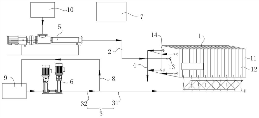
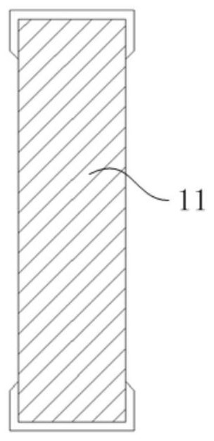
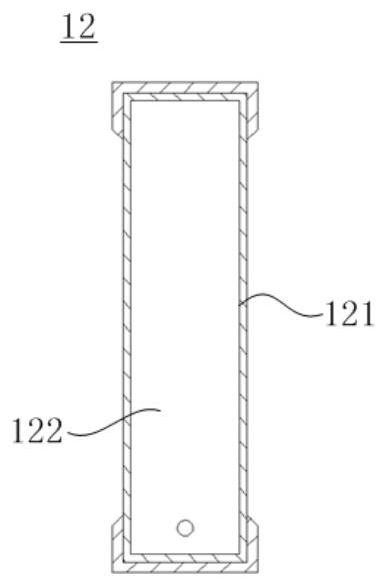
[0041] The invention provides a membrane filter press equipment, such as figure 1 As shown, the membrane filter press equipment includes a filter press 1, a mud inlet pipeline 2, a squeeze pipeline 3 and a water outlet pipeline 4, wherein the filter press 1 is provided with a filter chamber, and the filter chamber is provided with a mud inlet The port 13 and the water outlet 14 are provided with a plurality of box-type plates 11 and a plurality of diaphragm plates 12 in the filter press cavity, wherein each box-type plate 11 and the diaphragm plate 12 are sequentially spaced and staggered, and each box-type plate 11 and diaphragm The plates 12 are equipped with filter cloths, and filter chambers are formed between adjacen...


PUM


Abstract

The invention relates to membrane filter pressing equipment, a membrane filter pressing system and a membrane filter pressing method. The membrane filter pressing equipment comprises a filter press, asludge inlet pipeline, a squeezing pipeline and a water outlet pipeline,a filter pressing cavity of the filter press comprises a sludge inlet, a water outlet, a plurality of van-type plates and diaphragm plates, the van-type plates and the diaphragm plates are sequentially arranged at intervals in a staggered mode, a filtering cavity is formed between the adjacent van-type plates and diaphragm plates, and the filtering cavity is communicated with the sludge inlet and provided with a water filtering hole communicated with the water outlet. The sludge inlet pipeline is communicated with the sludge inlet and can be used for introducing sludge into the filtering cavity, the sludge inlet pipeline is provided with a first flow control part, the water outlet pipeline is communicated with the water outlet, the diaphragm plate comprises a diaphragm cavity and a diaphragm arranged on the side wall of the diaphragm cavity, the squeezing pipeline is communicated with the diaphragm cavity and canintroduce a squeezing medium into the diaphragm cavity, and the squeezing pipeline is provided with a second flow control part. The sludge filter pressing effect can be guaranteed, the water content of a filter cake is reduced, meanwhile, the situation that a membrane is torn and damaged due to excessive stretching is avoided, and the cost is reduced.

Description

technical field [0001] The invention relates to the field of filter press technology, in particular to a membrane filter press equipment, a membrane filter press system and a membrane filter press method. Background technique [0002] In the sludge dewatering industry, a diaphragm filter press is usually used to separate the sludge from solid and liquid. The filter box of the diaphragm filter press is composed of a plurality of box-type plates and diaphragm plates arranged at intervals. Each box-type plate and diaphragm plate It is equipped with a filter cloth, and a filter chamber is formed between the box plate and the diaphragm plate. The sludge enters the filter chamber to realize solid-liquid separation and the solid particles are intercepted by the filter cloth covering the surface of the filter plate (including the box plate and the diaphragm plate). And form a filter cake, the water in the sludge is discharged from the corner holes of the filter plate, and the solid-...

Claims


Application Information

Patent Timeline
IPC IPC(8): C02F11/122
CPCC02F11/122
Inventor 熊俊周旋辉肖炳坚
Owner 深圳包清天环保有限公司
Learn More