A roadway excavation method for electrode directional impact operation

A technology of electrodes and tunnels, which is applied in tunnels, earthwork drilling, mining equipment, etc., can solve the problems of slow tunneling progress in underground tunnels, unfavorable mine environmental protection and high-efficiency production, and affects the normal progress of tunneling projects, so as to reduce tunneling costs and ensure Safe and efficient production work, low-cost implementation

Active Publication Date: 2021-07-23
CHINA UNIV OF MINING & TECH
View PDF0 Cites 0 Cited by
  • Summary
  • Abstract
  • Description
  • Claims
  • Application Information

AI Technical Summary

Problems solved by technology

[0002] At this stage, my country's coal mining is mainly in the underground mining mode. In this mode, underground roadway excavation is the main process of mine mining. Underground roadway excavation has problems such as slow progress and high cost.
At present, mine roadway excavation mainly adopts full-face excavation method, drill and blast method, pilot tunnel method, partial excavation method and comprehensive excavation method; when mechanized excavation cannot be effectively implemented, blasting excavation method is usually used instead, but blasting The tunneling method is easy to cause secondary pollution, and has the disadvantages of high cost and complicated process, which is very unfavorable for the mine's environmental protection and efficient production work; in addition, in the traditional blasting tunneling method, the actual footage after blasting is about 1.0-1.5m, and the monthly The amount of excavation is only about 120-150m, the blasting efficiency is poor, the single-cycle blasting progress is low, the excavation is time-consuming and laborious, and the efficiency is slow, which affects the normal progress of the excavation project; therefore, there is an urgent need for a fast and effective method for rapid excavation of the roadway

Method used


Image

  • A roadway excavation method for electrode directional impact operation
  • A roadway excavation method for electrode directional impact operation

Examples


Embodiment Construction

[0033] The present invention will be further described below in conjunction with accompanying drawing.

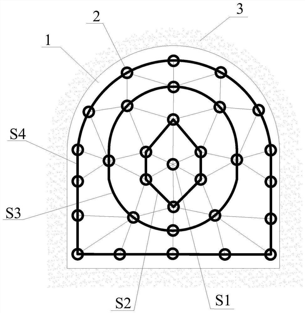
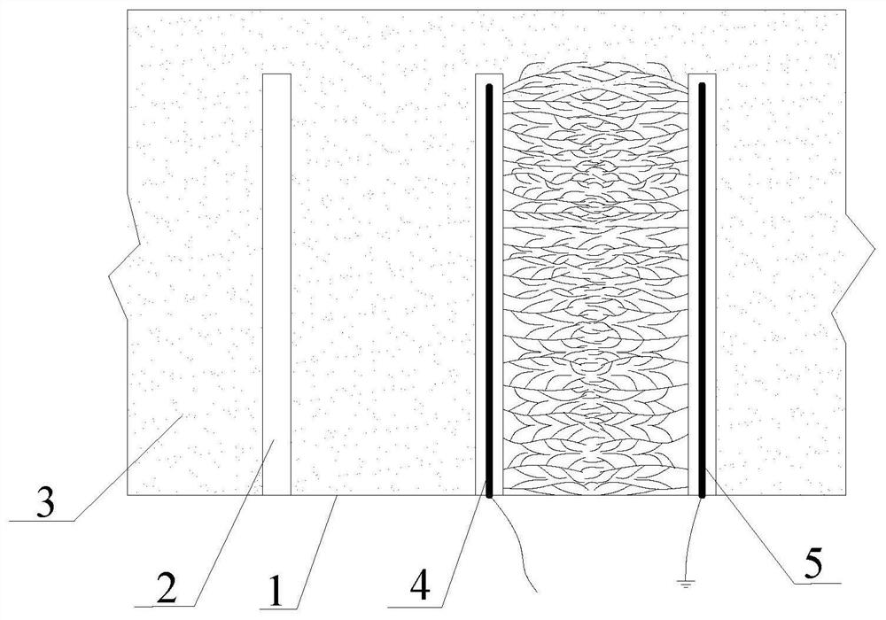
[0034] like figure 1 and figure 2 As shown, a roadway excavation method for electrode directional impact operation, specifically includes the following steps;

[0035] a. Several boreholes 2 are set on the roadway excavation surface 1, several boreholes 2 are spread over the roadway excavation surface 1, and the boreholes 2 are all perpendicular to the roadway excavation surface 1 and driven into the inside of the rock formation 3, and extend to the design Certain depth, several boreholes 2 are arranged as follows;

[0036] S11: laying out the first group of drilling holes S1;

[0037] Open a borehole 2 at the center of the roadway driving face 1;

[0038] S12: laying out the second group of drilling holes S2;

[0039] Arranging six boreholes 2 in a hexagonal arrangement around the outside of the borehole 2 at the central position;

[0040] S13: laying out the third ...


PUM


Abstract

A roadway excavation method for electrode directional impact operation, in which a borehole is opened on the roadway excavation surface; one borehole is opened in the center as the first group of boreholes; six boreholes are arranged outside the central borehole as the second group of boreholes, Eight drill holes are arranged outside the second group of drill holes as the third group of drill holes; sixteen drill holes are arranged outside the third group of drill holes as the fourth group of drill holes; Carry out rock-breaking operations with technology; carry out rock-breaking operations for holes drilled between the first and second groups of holes; carry out rock-breaking operations for any two adjacent holes in the second group of holes; carry out the second and third groups of holes Rock-breaking operations for drilling holes between groups of drilling holes; performing rock-breaking operations for any two adjacent drilling holes in the third group of drilling holes; performing rock-breaking operations for drilling holes between the third and fourth groups of drilling holes; Carry out the rock-breaking operation of any two adjacent drilling holes in the fourth group of drilling holes; clean up the rock and continue the follow-up rock-breaking operation. The method has simple steps, high excavation efficiency and low cost.

Description

technical field [0001] The invention belongs to the technical field of underground rock roadway excavation in mines, and in particular relates to a roadway excavation method for electrode directional impact operation. Background technique [0002] At present, my country's coal mining is mainly in the underground mining mode. In this mode, underground roadway excavation is the main process of mine mining. Underground roadway excavation has problems such as slow progress and high cost. At present, mine roadway excavation mainly adopts full-face excavation method, drill and blast method, pilot tunnel method, partial excavation method and comprehensive excavation method; when mechanized excavation cannot be effectively implemented, blasting excavation method is usually used instead, but blasting The tunneling method is easy to cause secondary pollution, and has the disadvantages of high cost and complicated process, which is very unfavorable for the mine's environmental protecti...

Claims


Application Information

Patent Timeline
Patent Type & Authority Patents(China)
IPC IPC(8): E21D9/10
CPCE21D9/10
Inventor 孙长伦李桂臣毕瑞阳孙元田荣浩宇许嘉徽梁巨理
Owner CHINA UNIV OF MINING & TECH
Why Eureka
Try Eureka