
Power takeoff assembly and application

A technology of power take-off and assembly, applied in the direction of clutch, machine/engine, mechanical drive clutch, etc., to achieve the effect of good reliability, avoiding difficulty in starting, and easy installation

Active Publication Date: 2021-01-05
SHAANXI FAST AUTO DRIVE GROUP CO LTD
View PDF8 Cites 1 Cited by
  • Summary
  • Abstract
  • Description
  • Claims
  • Application Information

AI Technical Summary

Problems solved by technology

[0004] Aiming at the technical problems existing in the prior art, the present invention provides a power take-off assembly and its application, which can reduce the load when the engine is started at low temperature in winter, thereby avoiding the problem of difficulty in starting the engine

Method used


Image

  • Power takeoff assembly and application
  • Power takeoff assembly and application
  • Power takeoff assembly and application

Examples


Embodiment Construction

[0030] In order to make the purpose, technical solutions and advantages of the embodiments of the present invention clearer, the technical solutions of the present invention will be clearly and completely described below in conjunction with the accompanying drawings. Obviously, the described embodiments are part of the embodiments of the present invention, not all of them. the embodiment. Based on the embodiments of the present invention, all other embodiments obtained by persons of ordinary skill in the art without making creative efforts belong to the protection scope of the present invention.

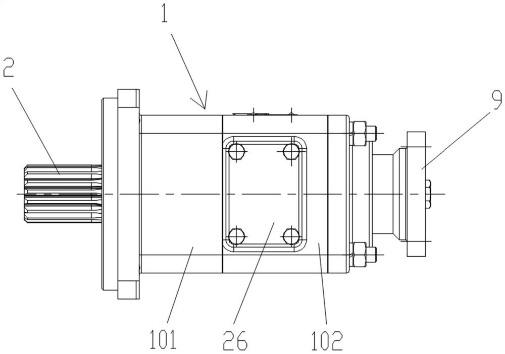
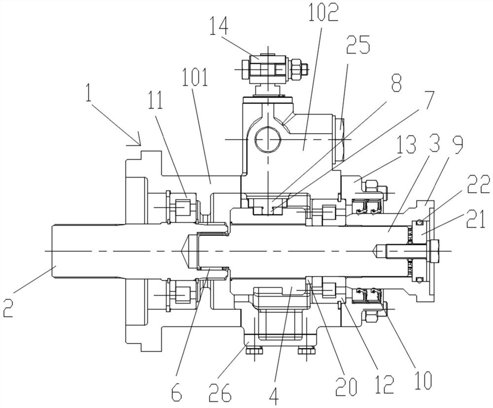
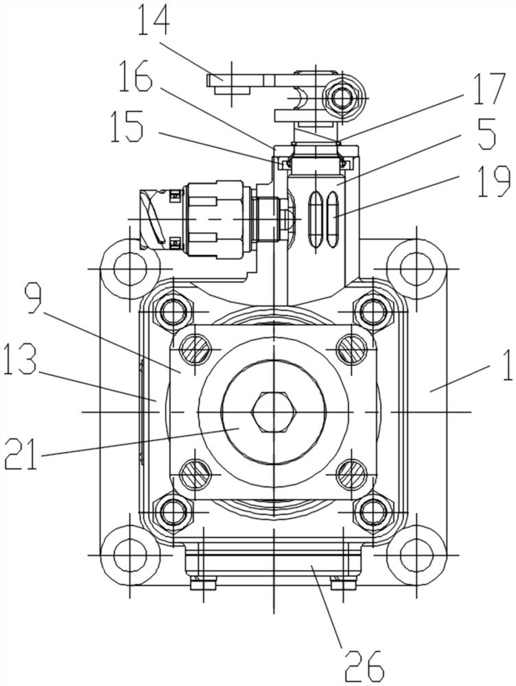
[0031] As a specific embodiment of the present invention, in combination with figure 1 , figure 2 , image 3 , Figure 4 and Figure 5 As shown, a power take-off assembly includes a power take-off housing 1. For ease of installation, the power take-off housing 1 includes a first housing 101 and a second housing 102 connected by bolts. Such as figure 2 As shown, the power take...


PUM


Abstract

The invention discloses a power takeoff assembly and application. The power takeoff assembly comprises a power takeoff shell, a power takeoff input shaft, a power takeoff output shaft, a sliding sleeve and a gear shifting shaft, wherein the power takeoff input shaft and the power takeoff output shaft are arranged in the power takeoff shell, one end of the power takeoff input shaft is rotationallyconnected with one end of the power takeoff output shaft, the other end of the power takeoff input shaft extends out of one end of the power takeoff shell and is used for being connected with a powertakeoff opening of a gearbox, and the other end of the power takeoff output shaft extends out of the other end of the power takeoff shell and is used for being connected with a hydraulic pump. Outer splines are arranged at the end, close to the power takeoff output shaft, of the power takeoff input shaft and the end, close to the power takeoff input shaft, of the power takeoff output shaft correspondingly, the sliding sleeve is provided with inner splines matched with the outer splines, and the rotating joint of the power takeoff input shaft and the power takeoff output shaft is sleeved with the sliding sleeve. One end of the gear shifting shaft extends into the power takeoff shell and is connected with the sliding sleeve. According to the power takeoff assembly, when an engine is startedat low temperature, the load can be reduced, and the problem that the engine is difficult to start is avoided.

Description

technical field [0001] The invention belongs to the technical field of power take-offs, and in particular relates to a power take-off assembly and its application. Background technique [0002] Xuzhong’s 100-ton cranes and off-road tire cranes often use AT gearboxes, and ZF gearboxes are commonly used. There is no clutch between the engine and the gearbox. The hydraulic pump is installed on the power take-off port of the gearbox. Disengage, that is to say, the hydraulic pump is in a state of always taking power. When the engine is started at low temperature in winter, for example, when the ambient temperature is below -15°C, the engine may be difficult to start due to the heavy load on the gearbox. [0003] Currently, there is no mature product on the market that can solve the problem of difficulty in starting the engine due to the excessive load of the gearbox. Contents of the invention [0004] Aiming at the technical problems in the prior art, the present invention pr...

Claims


Application Information

Patent Timeline
IPC IPC(8): F16D11/14F16H61/14F16H61/24F04B17/05
CPCF16D11/14F16H61/14F16H61/24F04B17/05F16D2011/002F16D2011/008
Inventor 武鑫严鉴铂刘义许先哲
Owner SHAANXI FAST AUTO DRIVE GROUP CO LTD
Learn More