Engineering surveying and marking device and method based on unmanned flying platform

A flying platform, engineering measurement technology, applied in measurement devices, radio wave measurement systems, aircraft, etc., can solve problems such as time-consuming, increased labor costs, failure to fundamentally eliminate potential safety hazards, and reduced work efficiency, reducing work efficiency. Time and economic cost, efficient movement across terrain obstacles, effect of increased efficiency

Pending Publication Date: 2021-01-05
NORTHWESTERN POLYTECHNICAL UNIV
View PDF1 Cites 6 Cited by
  • Summary
  • Abstract
  • Description
  • Claims
  • Application Information

AI Technical Summary

Problems solved by technology

Although this method has been improved compared with the traditional total station prism rod measuring device, there are still some shortcomings: (1) it does not fundamentally eliminate the potential safety hazards caused by the complex environment when the operator sets up the mark; (2) Although it can overcome the limitation brought by the length of the prism pole of the traditional total station to a certain extent, it still cannot completely overcome the difficulty of reaching the marking point caused by the complex and harsh geographical environment such as deep gullies and dangerous ravines, and the problem of inability to measure due to difficulty in erecting the mark; (3) The traditional measurement process requires two operators to work together. The operator who erects the marker needs to arrive at the site where the marker is erected. When crossing the steep terrain obstacles, the time and labor costs are greatly increased, which reduces the work efficiency.

Method used


Image

  • Engineering surveying and marking device and method based on unmanned flying platform
  • Engineering surveying and marking device and method based on unmanned flying platform
  • Engineering surveying and marking device and method based on unmanned flying platform

Examples


Embodiment Construction

[0031] Embodiments of the present invention are described in detail below, and the embodiments are exemplary and intended to explain the present invention, but should not be construed as limiting the present invention.

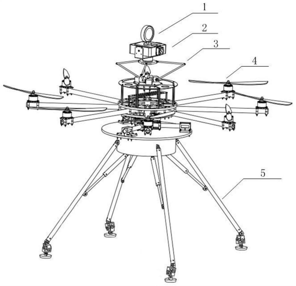
[0032] Such as figure 1 As shown, the device in this embodiment is mainly composed of a reflective prism 1, a three-axis stabilized pan-tilt 2, a servo lifting frame 3, an eight-rotor flying platform 4, and an all-terrain tripod 5. The reflective prism 1 is fixed on the top of the three-axis stable pan-tilt 2, and is used to reflect the light beam emitted by the photoelectric rangefinder, so as to calculate the distance between the point to be measured where the reflective prism 1 is located and the photoelectric rangefinder through the round-trip time of the beam; The axis-stabilized pan / tilt 2 is fixed on the servo lifting frame 3, which can drive the reflective prism 1 to rotate to the attitude angle specified by the surveyor; the servo lifting frame 3 is i...


PUM


Abstract

The invention provides an engineering surveying and marking device and method based on an unmanned flying platform. The engineering surveying and marking device is mainly composed of a multi-rotor flying platform, a three-axis stable holder, a servo lifting frame, an all-terrain foot stand, a reflecting prism and the like, wherein the reflecting prism is fixed at the top end of the three-axis stable holder and is used for reflecting a light beam emitted by a photoelectric range finder; the three-axis stable holder is fixed on the servo lifting frame and can drive the reflecting prism to rotateto a specified attitude angle; the servo lifting frame is installed on the flying platform, stretching is achieved through a two-section type folding structure, the stretching length of the servo lifting frame is controlled, and then the height of the reflecting prism is controlled; the flying platform is a carrier for realizing flying movement and fixed-point hovering of the whole device, and carries the reflecting prism to move across terrain obstacles in a large range in a horizontal plane; and the all-terrain foot stand is installed below the flying platform and is mainly used for observing and measuring the ground condition of an undetermined landing point and achieving horizontal landing and stabilization of a flight marking device on different terrains.

Description

technical field [0001] The patent of the present invention belongs to the field of engineering technology measurement, and specifically relates to an engineering measurement marking device based on an unmanned aerial platform. Background technique [0002] In the planning and construction stages of engineering construction projects, it is necessary to measure the height, angle, distance, orientation and mapping of the construction environment. In the process of carrying out these engineering measurements, an instrument is usually used—— The total station, that is, the total station electronic range finder, has been widely used in surveying and mapping, testing, monitoring and other measurement fields. When the total station is working, the photoelectric range finder emits an infrared beam to the leveled prism at the target point and then reflects it back. By measuring the time difference between the emitted beam and the return of the beam, the length of the beam propagation ...

Claims


Application Information

Patent Timeline
Patent Type & Authority Applications(China)
IPC IPC(8): G01S17/08G01C15/00G01C15/08G01B17/08G01B17/02B64C39/02B64C25/10
CPCB64C25/10B64C39/02G01B17/02G01B17/08G01C15/00G01C15/08G01S17/08
Inventor 高智刚李朋周军王超然张佼龙伍思欢霍大海杨玉嫣姜伟王启张沈钦邵茂森靳浩
Owner NORTHWESTERN POLYTECHNICAL UNIV
Why Eureka
Try Eureka