
Array substrate, display panel and display device

A technology for array substrates and display panels, which is applied in the fields of display panels, display devices, and array substrates, and can solve problems such as reducing the lower frame, achieving the effect of realizing narrow frame, reducing the space of wiring area, and realizing narrow frame design

Active Publication Date: 2021-01-05
KUNSHAN GO VISIONOX OPTO ELECTRONICS CO LTD
View PDF6 Cites 4 Cited by
  • Summary
  • Abstract
  • Description
  • Claims
  • Application Information

AI Technical Summary

Problems solved by technology

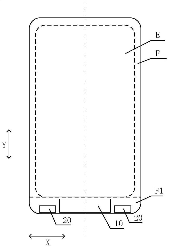
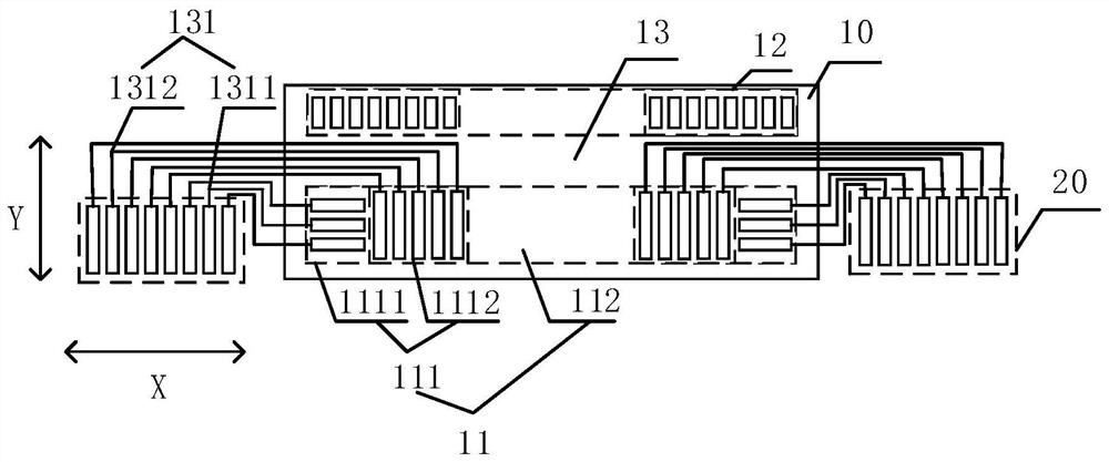
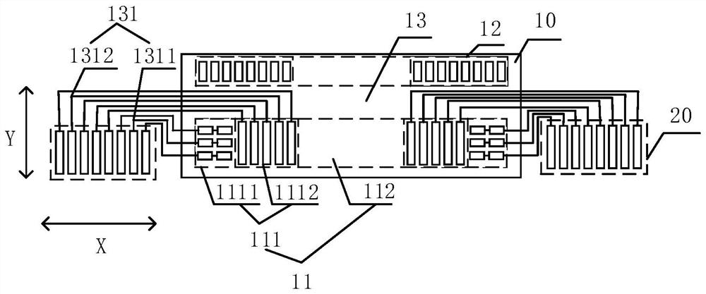
For the COG bonding solution, since both the driver chip (IC) and the flexible circuit board (FPC) need to be bound to the lower frame of the display panel, and the IC and the FPC need to be connected by wiring, the lower frame needs to be further reduced more difficult

Method used


Image

  • Array substrate, display panel and display device
  • Array substrate, display panel and display device
  • Array substrate, display panel and display device

Examples


Embodiment Construction

[0035] The characteristics and exemplary embodiments of various aspects of the present invention will be described in detail below. In order to make the purpose, technical solutions and advantages of the present invention clearer, the present invention will be further described in detail below in conjunction with the accompanying drawings and specific embodiments. It should be understood that the specific embodiments described here are only configured to explain the present invention, not to limit the present invention. It will be apparent to one skilled in the art that the present invention may be practiced without some of these specific details. The following description of the embodiments is only to provide a better understanding of the present invention by showing examples of the present invention.

[0036] It should be noted that in this article, relational terms such as first and second are only used to distinguish one entity or operation from another entity or operation...


PUM


Abstract

The invention discloses an array substrate, a display panel and a display device. A binding area of the array substrate comprises a driving chip binding area and a flexible circuit board binding area,the driving chip binding area is provided with a first bonding pad, the first bonding pad comprises a welding spot set and an isolation area, the welding spot set comprises a first welding spot set and a second welding spot set, the first welding spot set comprises a plurality of first welding spots arranged side by side in the first direction, the second welding spot set comprises a plurality ofsecond welding spots arranged side by side in the second direction, the second welding spot set is located between the first welding spot set and the isolation area, and the first welding spot set and the second welding spot set are connected with the flexible circuit board binding area through wires. And only the lead connected with the second welding spot set passes through the wiring area. Thelayout requirement of the wire for connecting the binding area of the flexible circuit board and the welding spot set can be met, the problems of difficult wiring, easy interference between signals and the like caused by insufficient wiring space are avoided, and the narrow frame design of the display panel is realized.

Description

technical field [0001] The present invention relates to the field of display technology, in particular to an array substrate, a display panel and a display device. Background technique [0002] In recent years, the full screen has become the mainstream design solution in the display field and is favored by consumers. In order to increase the screen-to-body ratio, the narrower the lower border of the display screen, the better. [0003] At present, there are three kinds of bonding solutions for the lower frame of the display screen: COG (chip on glass), COF (chip on FPC) and COP (chip on plastic). Although the frame is getting smaller and smaller, the cost is also getting higher and higher. Based on Considering the cost, the lower frame of the display screen currently on the market mainly adopts the COG (chip on glass) lamination scheme. For the COG bonding solution, since both the driver chip (IC) and the flexible circuit board (FPC) need to be bound on the lower frame of t...

Claims


Application Information

Patent Timeline
Patent Type & Authority Applications(China)
IPC IPC(8): G02F1/1345G09F9/30H01L51/52
CPCG02F1/13458G09F9/30H10K50/84
Inventor 许传志谢正芳吴勇
Owner KUNSHAN GO VISIONOX OPTO ELECTRONICS CO LTD
Learn More