Sliding mode control based current tracking method and system at output side of matrix converter

A matrix converter and current tracking technology, applied in control systems, vector control systems, control generators, etc., can solve the problems of vector control system performance degradation, poor anti-complex interference, etc., to improve control accuracy and anti-interference ability, Solve the effect of poor anti-complex interference and improve control performance

Active Publication Date: 2021-06-15
UNIV OF SCI & TECH BEIJING
View PDF0 Cites 0 Cited by
  • Summary
  • Abstract
  • Description
  • Claims
  • Application Information

AI Technical Summary

Problems solved by technology

[0004] The present invention provides a current tracking method and system at the output side of a matrix converter based on sliding mode control to solve the poor anti-complex interference of the vector control system of the permanent magnet synchronous motor of the robot. Technical issues that lead to performance degradation of vector control systems

Method used


Image

  • Sliding mode control based current tracking method and system at output side of matrix converter
  • Sliding mode control based current tracking method and system at output side of matrix converter
  • Sliding mode control based current tracking method and system at output side of matrix converter

Examples


no. 1 example

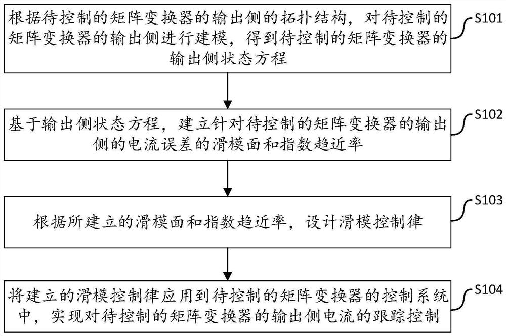
[0064] This embodiment provides a method for tracking current at the output side of a matrix converter based on sliding mode control. The method can be implemented by an electronic device, and the electronic device can be a terminal or a server. Such as figure 1 As shown, the execution flow of the current tracking method at the output side of the matrix converter based on sliding mode control includes the following steps:

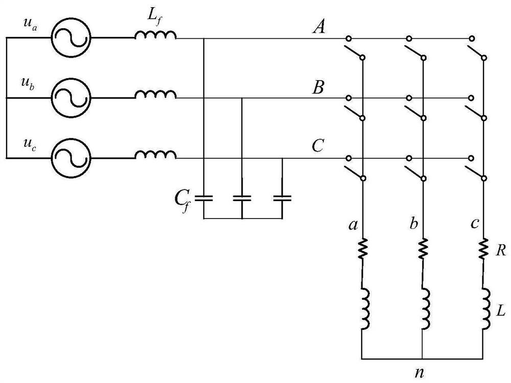
[0065] S101. Modeling the output side of the matrix converter to be controlled according to the topology structure of the output side of the matrix converter to be controlled to obtain a state equation of the output side of the matrix converter to be controlled;

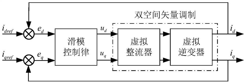
[0066] S102, based on the output side state equation, establishing a sliding mode surface and an exponential approach rate for the current error at the output side of the matrix converter to be controlled;

[0067] S103, designing a sliding mode control law according to the established sliding mo...

no. 2 example

[0091] This embodiment provides a matrix converter output side current tracking system based on sliding mode control, the matrix converter output side current tracking system based on sliding mode control includes the following modules:

[0092] A matrix converter output side modeling module, configured to model the output side of the matrix converter to be controlled according to the topology structure of the output side of the matrix converter to be controlled, to obtain the matrix converter to be controlled The output side state equation of ;

[0093] A sliding mode surface and exponential rate of approach establishment module, configured to establish a sliding mode surface and an exponential rate of approach for the current error on the output side of the matrix converter to be controlled based on the state equation of the output side;

[0094] The sliding mode control law design module is used to design the sliding mode control law according to the established sliding mod...

no. 3 example

[0098] This embodiment provides an electronic device, which includes a processor and a memory; at least one instruction is stored in the memory, and the instruction is loaded and executed by the processor, so as to implement the method of the first embodiment.

[0099]The electronic device may have relatively large differences due to different configurations or performances, and may include one or more processors (central processing units, CPU) and one or more memories, wherein at least one instruction is stored in the memory, so The above instructions are loaded by the processor and perform the following steps:

[0100] S101. Modeling the output side of the matrix converter to be controlled according to the topology structure of the output side of the matrix converter to be controlled to obtain a state equation of the output side of the matrix converter to be controlled;

[0101] S102, based on the output side state equation, establishing a sliding mode surface and an exponen...


PUM


Abstract

The invention discloses a method and system for tracking current at the output side of a matrix converter based on sliding mode control. The method includes building the output side of the matrix converter to be controlled according to the topology Modulus, obtain the output side state equation of the matrix converter to be controlled; Based on the output side state equation, establish the sliding mode surface and the exponential approach rate for the current error of the output side of the matrix converter to be controlled; According to the established Sliding mode surface and exponential rate of approach, design sliding mode control law; Apply the sliding mode control law of establishment to the control system of the matrix converter to be controlled, realize the output to the matrix converter to be controlled Side current tracking control. The invention can effectively improve the output current performance of the matrix converter under the abnormal working conditions of asymmetrical three-phase input voltage and unbalanced three-phase load.

Description

technical field [0001] The invention relates to the technical field of matrix converter control, in particular to a current tracking method and system at the output side of a matrix converter based on sliding mode control. Background technique [0002] Matrix converter is a complex flexible power electronic converter, which can realize the conversion of various parameters (phase number, phase, amplitude, frequency) of alternating current. Compared with traditional converters, it has the following advantages: no intermediate DC energy storage link; four-quadrant operation; excellent input current waveform and output voltage waveform; freely controllable power factor. At present, the matrix converter has become one of the hot spots in the research of power electronics technology, and has broad development prospects in the field of AC-AC conversion. [0003] Since the matrix converter omits the intermediate energy storage link, the output current performance is very easily aff...

Claims


Application Information

Patent Timeline
Patent Type & Authority Patents(China)
IPC IPC(8): H02P21/00H02P21/22H02P27/16H02M5/06
CPCH02P21/0007
Inventor 潘月斗王阳阳
Owner UNIV OF SCI & TECH BEIJING
Why Eureka
Try Eureka