Reverse connection self-correcting circuit and electric equipment

A technology for electrical equipment and circuits, applied in circuits, relays, electrical components, etc., can solve problems such as affecting the normal use of the load and cannot be reversed and corrected.

Pending Publication Date: 2021-01-05
GREE ELECTRIC APPLIANCES INC
View PDF0 Cites 0 Cited by
  • Summary
  • Abstract
  • Description
  • Claims
  • Application Information

AI Technical Summary

Problems solved by technology

[0004] In the embodiment of the present invention, a reverse connection self-correcting circuit and electrical equipment are provided to solve the problem that the reverse connection cannot be automatically corrected in the prior art and affect the normal use of the load

Method used


Image

  • Reverse connection self-correcting circuit and electric equipment
  • Reverse connection self-correcting circuit and electric equipment
  • Reverse connection self-correcting circuit and electric equipment

Examples


Embodiment 1

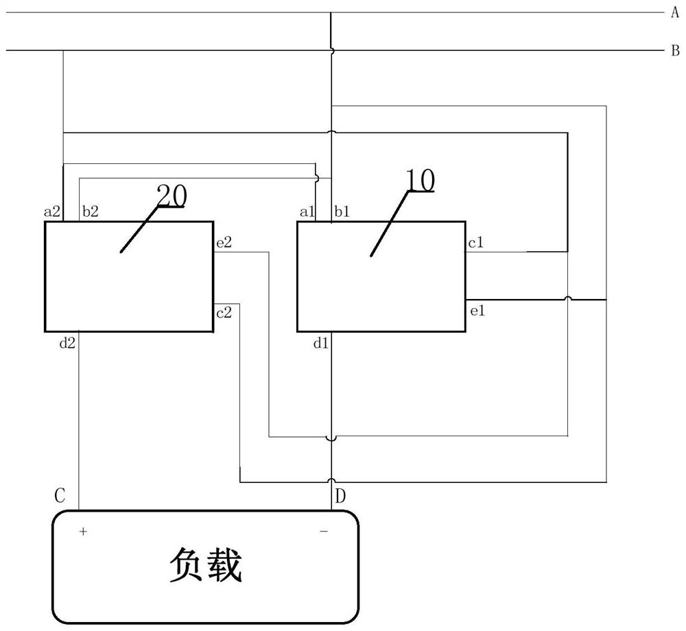
[0033] This embodiment provides a reverse connection self-correcting circuit, figure 1 It is a structural diagram of a reverse connection self-correcting circuit according to an embodiment of the present invention, such as figure 1 As shown, the circuit includes:

[0034] The first switch module 10 has its first input terminal a1 connected to the second line B of the power supply, its second input terminal b1 connected to the first line A of the power supply, and its third input terminal c1 connected to the second line B of the power supply, Its first output terminal d1 is connected to the negative terminal D of the load, and its second output terminal e1 is connected to the first line A of the power supply. Power-off state, that is, switch the conduction state between the third input terminal c1 and the second output terminal e1, and then control its own first input terminal a1 or second input terminal b1 to alternatively conduct with the first output terminal d1 ; The circ...

Embodiment 2

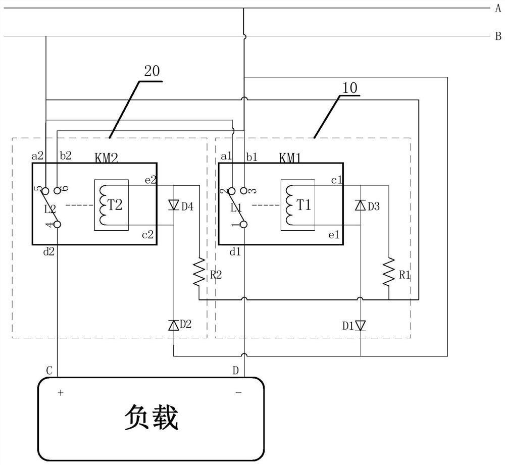
[0038] This embodiment provides another reverse connection self-correcting circuit, figure 2 It is a structural diagram of a reverse connection self-correcting circuit according to another embodiment of the present invention. In order to match the two lines of the power supply with the positive and negative terminals D of the load respectively, as figure 2 As shown, so that in this embodiment, the first switch module 10 is powered off when the polarity of the first line A of the power supply is positive and the polarity of the second line B is negative, the third input terminal c1 and the second output terminal Disconnect between e1, and then control its own first input terminal a1 and first output terminal d1 to conduct, because the first input terminal a1 of the first switch module 10 is connected to the second line B, and the first output terminal d1 is connected to the negative terminal of the load D. Therefore, through the above scheme, it is ensured that the second lin...

Embodiment 3

[0048] This patent proposes a reverse connection self-correcting circuit, as mentioned above figure 1 As shown in , the power supply voltage is input by the first line A and the second line B to supply power for the above-mentioned reverse connection self-correcting circuit and the load. The reverse polarity self-correcting circuit includes a first switch module 10, a second switch module 20 and a polarity load (ie, the load in the above embodiments). The output current of the power supply passes through the first switch module 10 and the second switch module 20 to supply power for polar loads.

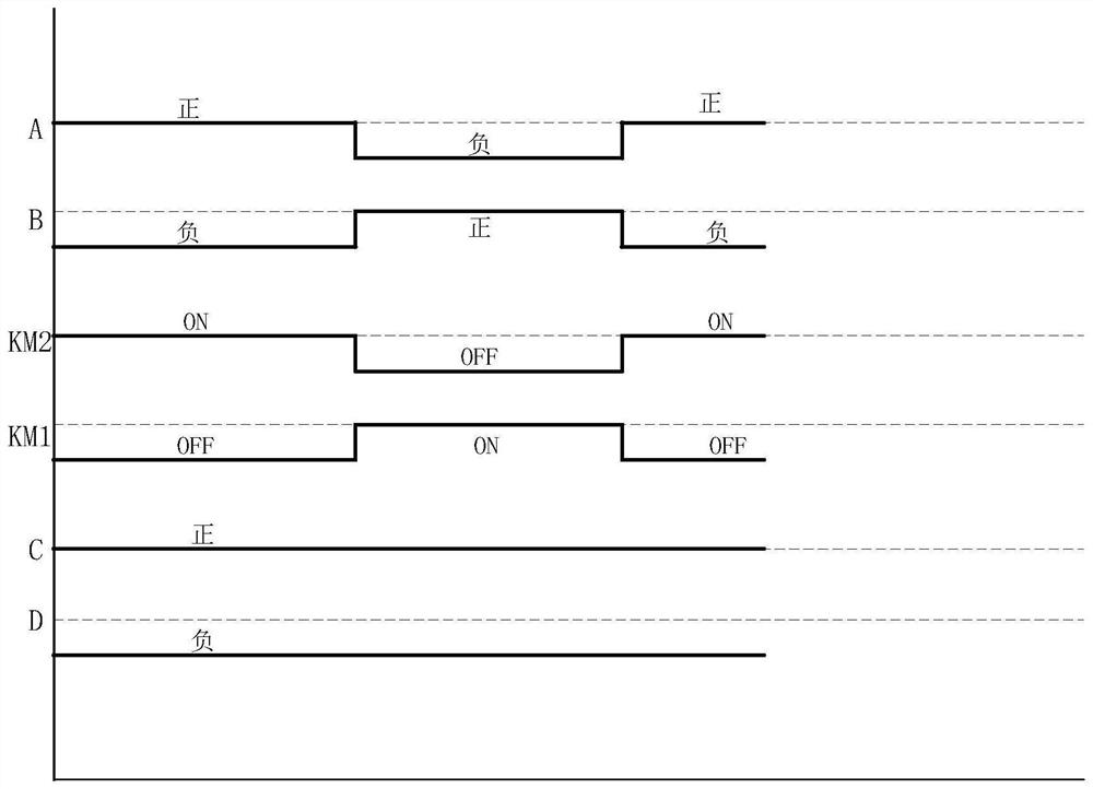
[0049] The specific circuit structure of this embodiment is as mentioned above figure 2 shown in . Its specific working principle is as follows:

[0050] Both the first relay KM1 and the second relay KM2 have a single set of contacts. When no power is applied, the second contact 2 is connected to the first contact 1, and the fifth contact 5 is connected to the fourth contact 4. ....


PUM


Abstract

The invention discloses a reverse connection self-correcting circuit and electric equipment. The circuit comprises a first switch module of which the first input end and the third input end are connected with a second line of a power supply, the second input end and the second output end are connected with a first line of the power supply, and the first output end is connected with a negative terminal of a load, and which is used for controlling the first input end or the second input end to bealternatively conducted with the first output end according to polarities of the first line and the second line; a second switch module of which the first input end and the second output end are connected with the second line of the power supply, the second input end and the third input end are connected with the first line of the power supply, and the first output end is connected with the positive terminal of the load, and which is used for controlling the first input end or the second input end to be alternatively conducted with the first output end according to the polarities of the first line and the second line. According to the circuit, automatic correction after reverse connection canbe realized, and normal use of the load can be ensured all the time.

Description

technical field [0001] The invention relates to the technical field of electronic power, in particular to a reverse connection self-correcting circuit and electrical equipment. Background technique [0002] When polar loads such as commonly used semiconductor devices, sensor devices or communication devices are connected to the two wires of the power supply, the requirements for polarity matching must be met. The load will not work properly and may cause damage in severe cases. For example, in the actual testing and development process of the wireless communication mesh network, it is found that when the positive and negative poles of the power line of the communication device are reversed, it is easy to cause the controller board to fail to work normally or the communication device to be damaged. The existing anti-reverse connection circuit , the circuit does not conduct after the reverse connection, which can protect the load, but it cannot automatically correct the rever...

Claims


Application Information

Patent Timeline
Patent Type & Authority Applications(China)
IPC IPC(8): H03K17/51H03K17/76H03K17/00H01H47/00
CPCH01H47/00H03K17/002H03K17/51H03K17/76H03K2017/515
Inventor 王玉玺金国华叶唤涛黄强黄佳星
Owner GREE ELECTRIC APPLIANCES INC
Why Eureka
Try Eureka