Camera debugging device and method

A debugging method and camera technology, applied in the field of optical inspection, can solve problems such as complicated debugging process, long cycle, difficult camera adjustment, etc., to achieve the effect of reducing workload, improving accuracy, and avoiding multiple acquisitions

Pending Publication Date: 2021-01-05
THUNDERSOFT
View PDF0 Cites 2 Cited by
  • Summary
  • Abstract
  • Description
  • Claims
  • Application Information

AI Technical Summary

Problems solved by technology

[0004] see figure 1 At present, distortion correction needs to take multiple shots of the checkerboard calibration pattern, analyze the distortion according to the captured image, and then import the corrected parameter file into the camera through other equipment to correct the distortion of the camera. It is difficult to adjust the camera and the debugging process is complicated. , long cycle and other technical problems

Method used


Image

  • Camera debugging device and method
  • Camera debugging device and method
  • Camera debugging device and method

Examples


Embodiment 1

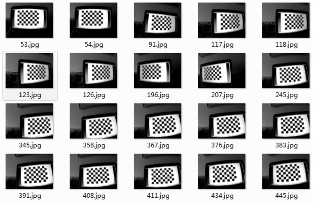
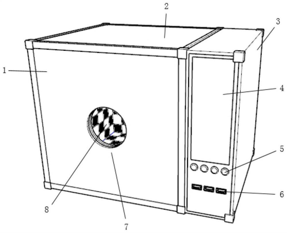
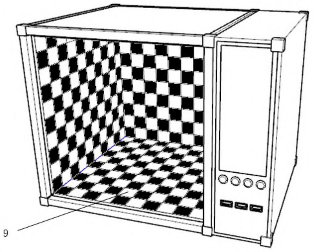
[0055]according toFigure 2-5As shown, Embodiment 1 discloses a camera debugging device for camera testing or correction. Embodiment 1 records an embodiment that only includes a light box in the camera debugging device. It should be noted that the camera in this embodiment It can be a camera in an electronic device such as a mobile phone, or can be applied to a lens in a camera. There is no specific limitation here. The debugging includes but not limited to camera testing such as imaging quality tuning test, parameter testing, and camera correction such as distortion correction.

[0056]The light box includes a front cover plate 1 and a preset image display part 2. The front cover plate 1 and the preset image display part 2 are assembled together to enclose the inner space of the light box. The inner side of the preset image display part 2 is provided with a calibration pattern, Preferably, the calibration pattern occupies all the inner area of ​​the preset image display component, so t...

Embodiment 2

[0066]SeeFigure 2-5, Embodiment 2 discloses a computing device 3 for camera debugging. The computing device 3 is a special computer designed for camera debugging. The computing device includes a circuit board, a processor, a register, a disk, a power supply, an interface, and Data bus, etc. Specifically, the computing device 3 includes a box with a display screen 4, a knob / button 5, and a data interface 6, and a processor, a register, a data bus, and other devices used for calculation and communication are arranged in the box.

[0067]Among them, the processor can be used to test or correct the camera to be debugged, and determine the test or correction result.

[0068]The display screen 4 is used to monitor the test or correction process of the camera to be debugged, and display the images collected by the camera to be debugged and the image test or correction result. The display screen 4 is preferably a touch screen to facilitate control of the test or correction process.

[0069]The multi...

Embodiment 3

[0074]See alsoFigure 2-5, Embodiment 3 discloses a camera debugging device that fixes the computing device and the light box together. The device is composed of the light box of Embodiment 1 and the computing device of Embodiment 2, wherein the light box and the computing device can be Screws or screws or glue are fixedly connected together and used in conjunction with the test analysis or correction of the camera.

[0075]When in use, the specific cooperation mode of the light box and the computing device and the realized debugging function may not be specifically limited.

[0076]Embodiment 3 of the present invention combines a light box and a computing device, can combine the calibration pattern collection process with the analysis processing process, and supports real-time adjustment of the entire test or correction process through the display screen and knob keys. It greatly reduces the workload of data transmission and transfer during collection to analysis, and greatly improves the...


PUM


Abstract

The invention discloses a camera debugging device and method. The camera debugging equipment comprises a front cover plate and a preset image display part, wherein the front cover plate and the presetimage display part form an internal space of a lamp box in a surrounding manner; a camera shooting opening is formed in the front cover plate, and the camera shooting opening can enable a to-be-debugged camera to shoot the internal space of the lamp box; and the preset image display part comprises a calibration plate located on the inner side and a light-emitting plate located on the outer side of the calibration plate, and a calibration pattern for camera debugging is preset on the inner side face of the calibration plate. According to the technical scheme, the novel camera debugging equipment is provided, the adjustment frequency can be reduced, camera image quality optimization tests and parameter tests such as chromatic aberration, contrast and white balance can be rapidly and efficiently achieved, and the novel camera debugging equipment is particularly suitable for distortion correction of the camera when the camera leaves a factory.

Description

Technical field[0001]The invention belongs to the technical field of optical detection, and particularly relates to a camera debugging device and method.Background technique[0002]With the rapid development of electronic devices represented by mobile phones, the image capture function has become one of the important functions of consumer electronics. At the same time, with the completion of 4G coverage and the acceleration of 5G, video and short videos have become the main forms of content exchange. Video conferencing The demand for video and live broadcast is increasing day by day, and the application and demand for cameras are increasing day by day.[0003]The camera is assembled from multiple parts. After the camera is assembled, a number of tests need to be performed on the camera to ensure that the camera is of qualified quality before leaving the factory. The distortion test of the camera is an important test at the factory. At the same time, at the end of the camera use, differe...

Claims


Application Information

Patent Timeline
Patent Type & Authority Applications(China)
IPC IPC(8): H04N17/00
CPCH04N17/002
Inventor 宋卫华刘心鹏
Owner THUNDERSOFT
Why Eureka
Try Eureka