Low-clearance adjustable suspension wire clamp

A hanging wire clip, low headroom technology, applied in overhead lines and other directions, can solve the problems of inability to adapt to low headroom tunnel installation, large structure height, etc., and achieve the effect of shortening construction operation time, saving installation space and accurate positioning

Pending Publication Date: 2021-01-08
CHINA RAILWAY HIGH SPEED ELECTRIFICATION EQUIP CORP LTD +1
View PDF2 Cites 2 Cited by
  • Summary
  • Abstract
  • Description
  • Claims
  • Application Information

AI Technical Summary

Problems solved by technology

The currently disclosed "conductive rail holding device" (CN201080055910.X) and "an automatic adjustable elastic suspension clamp along the line" (CN201910993990.6) have the function of swinging a certain angle along the line direction, but their swing The hinge points are all located at the lower part of the suspension clamp, resulting in a large overall structure height, which cannot be adapted to the installation of low-clearance tunnels

Method used


Image

  • Low-clearance adjustable suspension wire clamp
  • Low-clearance adjustable suspension wire clamp
  • Low-clearance adjustable suspension wire clamp

Examples


Embodiment Construction

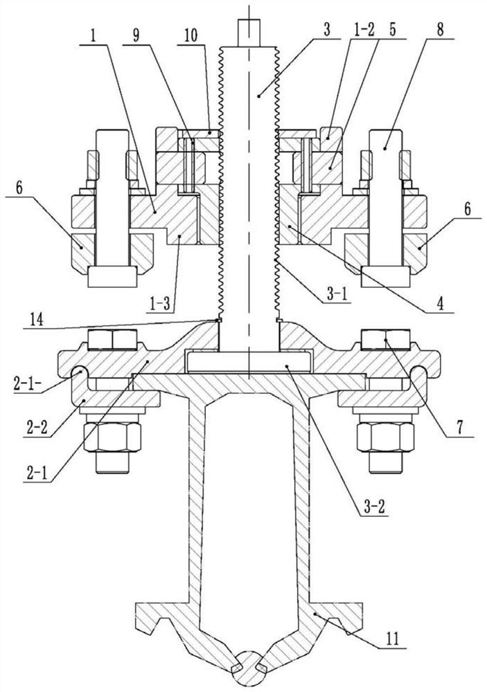
[0023] Attached below Figure 1-6 The present invention will be described in detail with specific embodiments.

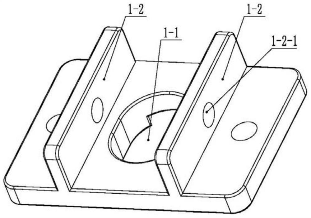
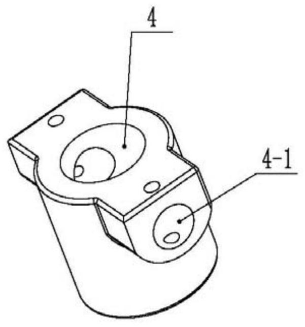
[0024] A low headroom adjustable suspension clamp, comprising a connection seat 1 and a bus cable clamp 2; the upper end surface of the connection seat 1 has two ears 1-2, and there is a line between the two ears 1-2 Bar-shaped hole 1-1; the upper end of the internal thread sleeve 4 is hinged between the ears 1-2, the lower end is inserted in the bar-shaped hole 1-1, and the internal thread sleeve 4 can be placed in the bar-shaped hole 1-1 around the hinge point Swing back and forth in the middle; the upper end of the external thread adjustment shaft 3 is threadedly connected with the internal thread sleeve 4, and the lower end is hingedly connected with the busbar clamp 2, and the busbar clamp 2 is suspended under the connection seat 1, and the busbar clamp 2 can be wound around the outside Thread adjustment shaft 3 rotates horizontally.

[0025] In one of the em...


PUM


Abstract

A low-clearance adjustable suspension wire clamp comprises a connecting base and a busbar wire clamp. Double lugs are arranged on the upper end face of the connecting base, and a strip-shaped hole inthe line direction is formed between the double lugs; the upper end of an internal thread bushing is hinged between the two lugs, the lower end of the internal thread bushing is inserted into the strip-shaped hole, and the internal thread bushing can swing back and forth in the strip-shaped hole around a hinge point; the upper end of an external thread adjusting shaft is in threaded connection with the internal thread sleeve, the lower end of the external thread adjusting shaft is hinged to the busbar wire clamp, and the busbar wire clamp is hung below the connecting base and can horizontallyrotate around the external thread adjusting shaft. The swinging hinge point is moved upwards, the height of the whole structure is reduced, the use requirement of low-clearance tunnel installation ismet, and installation and adjustment are convenient.

Description

technical field [0001] The invention belongs to the technical field of rail transit rigid suspension systems, and in particular relates to a low headroom adjustable suspension clamp. Background technique [0002] Rigid suspension system is adopted by more and more lines due to its characteristics of less maintenance, long service life, and no-tension erection of contact wires. Suspension busbar. The currently disclosed "conductive rail holding device" (CN201080055910.X) and "an automatic adjustable elastic suspension clamp along the line" (CN201910993990.6) have the function of swinging a certain angle along the line direction, but their swinging The hinge points are all located at the lower part of the suspension clamps, resulting in a large overall structure height, which cannot be adapted to the installation of low-clearance tunnels. Contents of the invention [0003] The invention provides a low headroom adjustable suspension clamp, which moves up the swing hinge poi...

Claims


Application Information

Patent Timeline
Patent Type & Authority Applications(China)
IPC IPC(8): B60M1/20B60M1/24
CPCB60M1/20B60M1/24
Inventor 冯勇林建徐鸿燕邓相龙黄冬亮单翀皞刘娟王刘辉何花蕾王璐李士杰
Owner CHINA RAILWAY HIGH SPEED ELECTRIFICATION EQUIP CORP LTD
Why Eureka
Try Eureka