

Cable turning system formation and ascending method thereof
A technology of forward direction and revolution speed, applied in the fields of rocket launch, aerospace, and satellite, it can solve the problems of large centrifugal force, difficulty in increasing the outward movement multiple of the transfer cable system, and increasing the revolution speed of the load.
- Summary
- Abstract
- Description
- Claims
- Application Information
AI Technical Summary
Problems solved by technology
Method used
Image

Examples
Embodiment 11
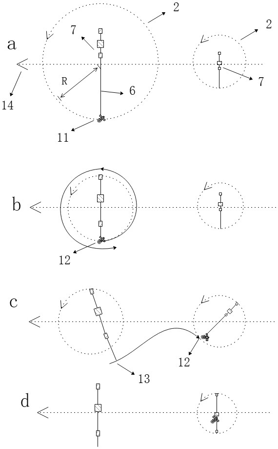
[0079] A cable formation is composed of two cable systems 7, that is, N=2. The transfer cable system 7 refers to the external transfer transfer cable system 7 or the space transfer cable system 7. The transfer cable system 7 has a main rope 6, and the main rope 6 is used to move the traction load 11 inwardly or outwardly.
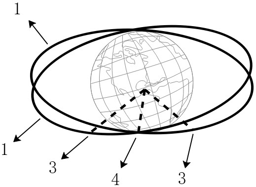
[0080] The two orbits 1 have an encounter area 4 where the two cable systems 7 appear simultaneously, where the distance between the centroids of the two cable systems 7 is 180 km, and the difference in altitude is less than 30 km.
[0081] Such as figure 1 As shown, the encounter area 4 is in the middle of the perigee point 3 of the revolution orbit of the two transfer cable systems 7 . The distance between the perigees of the revolution orbits of the two cable systems is 600km, and the distance between the apogees is 1200km.
[0082] The included angle between the connection line between the center of the earth in the encounter area 4 and the line betwe...
Embodiment 12
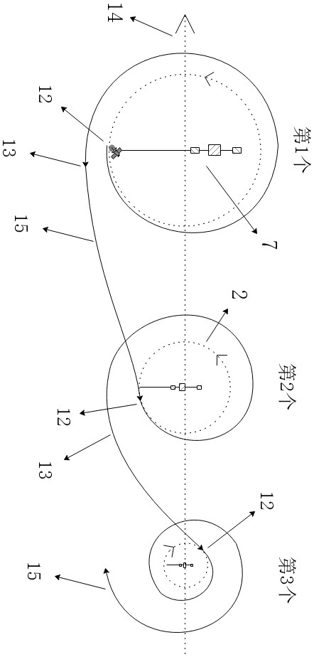
[0087] The formation has 3 transfer cable systems 7, that is, N=3, such as image 3 shown. The rotation plane of each cable system 7 coincides with the revolution plane; the revolution track 1 of the centroid of each cable system 7 coincides, and each cable system 7 is arranged front and back. Therefore, the revolution periods and revolution speeds of the respective switchable cable systems 7 are exactly the same, and the latter switchable cable systems 7 follow the first switchable cable system 7 to advance. The encounter area 4 is the perigee 3 of the revolution track 1 of each cable system 7 .
[0088] For the formation whose revolution orbit 1 coincides, the encounter area 4 is everywhere, and the perigee 3 is the most ideal place for docking with the launch vehicle. Therefore the area of encounter refers only to the perigee.
[0089] The first transfer cable system 7 is at the front of the formation, the second transfer cable system 7 is at the second position, and t...
Embodiment 13
[0096] Each cable transfer system 7 has a quick-diameter-changing device. The quick-diameter-changing device has a hoist that is an energy-dissipating hoist. The energy-dissipating hoist winds the main rope 6 and pulls the load 11, which can quickly move the load outward.
[0097] Such as image 3 The 1st and 2nd conversion cable system 7. The first transfer cable system 7 is at the front of the formation, the second transfer cable system 7 is at the second position, and the third transfer cable system 7 is at the end.
[0098] The rotation directions of the first and second cable transfer systems 7 are the same, and they all rotate counterclockwise. The so-called revolution and rotation directions refer to clockwise or counterclockwise directions. Both systems either revolve and rotate clockwise, or revolve and rotate counterclockwise.
[0099] The spacecraft 11 breaks away from the lower point at the end of the main rope 6 of the first transfer cable system 7 . The rotat...
PUM
 Abstract
Description
Claims
Application Information