
Structure and construction method of newly-added prefabricated guardrail of existing bridge

A construction method and guardrail technology, applied in bridges, bridge parts, bridge maintenance, etc., can solve problems such as poor anti-collision ability of guardrails, difficulty in effective combination, and bridge traffic interference, so as to improve anti-collision ability, strengthen anti-collision ability, The effect of reducing distractions

Pending Publication Date: 2021-01-08
GUANGZHOU MUNICIPAL ENG DESIGN & RES INST CO LTD
View PDF0 Cites 0 Cited by
  • Summary
  • Abstract
  • Description
  • Claims
  • Application Information

AI Technical Summary

Problems solved by technology

[0003] In the prior art, the method of adding guardrails to the existing bridges is usually to remove the existing guardrails under the condition of enclosing the traffic, then form a mold on the bridge, and then form a new guardrail in the mold by cast-in-place. The technical defect of the guardrail is that the construction speed is slow and the work area involved is large, which seriously interferes with the bridge traffic
[0004] In the existing technology, there is a manufacturing technology of concrete prefabricated parts, which can shorten the time required for on-site construction. The technical defect is that it is difficult to effectively combine the usual concrete prefabricated part installation structure with the existing bridge structure, resulting in The guardrail has poor anti-collision ability

Method used


Image

  • Structure and construction method of newly-added prefabricated guardrail of existing bridge
  • Structure and construction method of newly-added prefabricated guardrail of existing bridge
  • Structure and construction method of newly-added prefabricated guardrail of existing bridge

Examples


Embodiment Construction

[0036] This part will describe the specific embodiment of the present invention in detail, and the preferred embodiment of the present invention is shown in the accompanying drawings. Each technical feature and overall technical solution of the invention, but it should not be understood as a limitation on the protection scope of the present invention.

[0037] In the description of the present invention, it should be understood that the orientation descriptions, such as up, down, front, back, left, right, etc. indicated orientations or positional relationships are based on the orientations or positional relationships shown in the drawings, and are only In order to facilitate the description of the present invention and simplify the description, it does not indicate or imply that the device or element referred to must have a specific orientation, be constructed and operated in a specific orientation, and thus should not be construed as limiting the present invention.

[0038] I...


PUM


Abstract

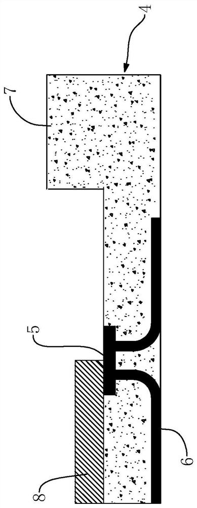
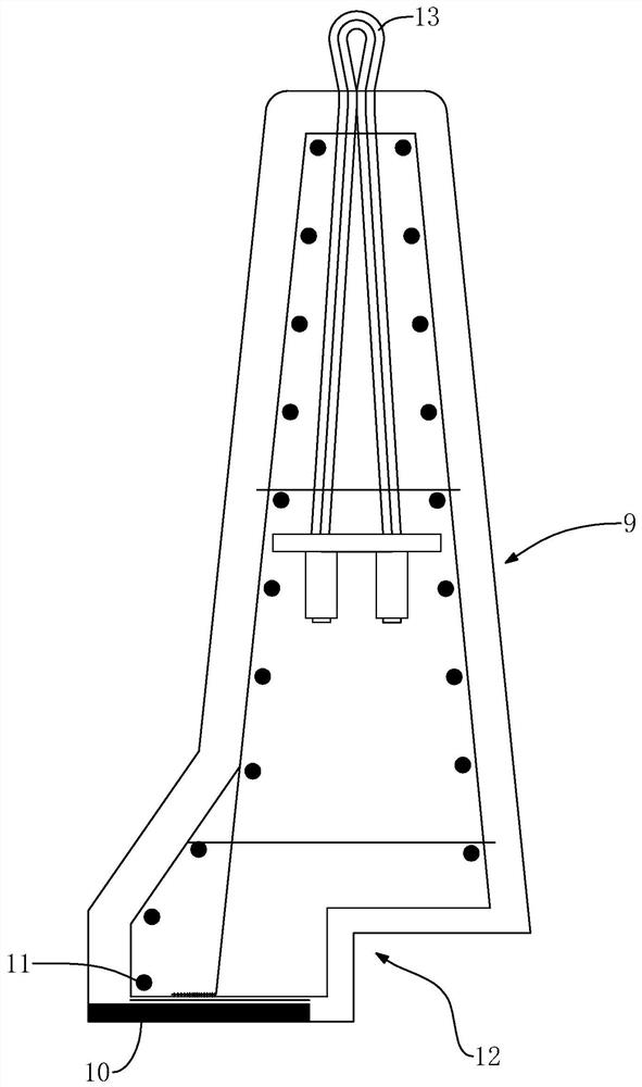
The invention discloses a structure and a construction method of a newly-added prefabricated guardrail of an existing bridge. The structure of the newly-added prefabricated guardrail of the existing bridge comprises a main beam, wherein a plurality of first reinforcing steel bars are arranged in the main beam; a base, wherein a first steel plate and a plurality of second reinforcements are arranged in the base, and the second reinforcements are connected with the first reinforcements and the first steel plate; a guardrail which is provided with a second steel plate and a plurality of third reinforcing steel bars, the third reinforcing steel bars are embedded into the guardrail, the second steel plate is connected with the third reinforcing steel bars, the second steel plate is connected with the first steel plate, a shear key and a shear groove are arranged between the guardrail and the base, and the shear key can be embedded into the shear groove. The structure has the beneficial effects that the second steel plate and the third steel plate enable the base and the guardrail body to be connected, a stable structure can be formed between the guardrail body and the base through shearkeys and shear groove structures, and the anti-collision capacity of the guardrail body can be improved advantageously; the guardrail can be obtained through a prefabricating method, the constructionprogress can be accelerated, and interference to bridge traffic can be reduced. The invention relates to bridge engineering.

Description

technical field [0001] The invention relates to bridge engineering, in particular to the structure and construction method of adding prefabricated guardrails to existing bridges. Background technique [0002] Guardrails are usually provided on bridges, and the guardrails have anti-collision functions. During the use of the bridge, factors such as the impact of the guardrail in traffic accidents and the return of concrete strength will cause the guardrail to be damaged to varying degrees, which will form a safety hazard, so it is necessary to repair the guardrail. [0003] In the prior art, the method of adding guardrails to the existing bridges is usually to remove the existing guardrails under the condition of enclosing the traffic, then form a mold on the bridge, and then form a new guardrail in the mold by cast-in-place. The technical defect of the guardrail is that the construction speed is slow and the work area involved is large, which seriously interferes with the br...

Claims


Application Information

Patent Timeline
IPC IPC(8): E01D22/00E01D19/10
CPCE01D19/103E01D22/00
Inventor 刘小刚熊勇曾储惠
Owner GUANGZHOU MUNICIPAL ENG DESIGN & RES INST CO LTD
Learn More