A rotary compensator with flexible rotation and high pressure resistance

A rotary compensator and high-pressure-resistant technology, which is applied in expansion compensation devices for pipelines, adjustable connections, passing components, etc., can solve the problems of high erection cost, inability to set up, general high-pressure resistance, etc., and improve the flexibility of rotation High performance, good rotation flexibility, and smooth rotation process

Active Publication Date: 2022-03-22
江苏恒昌波纹管有限公司
View PDF6 Cites 0 Cited by
  • Summary
  • Abstract
  • Description
  • Claims
  • Application Information

AI Technical Summary

Problems solved by technology

[0002] With the development of urban industry, thermal pipelines and petrochemical pipelines are also being updated day by day. Especially in recent years, many long-distance compensation pipelines and three-dimensional pipelines have appeared. Especially in the space pipe network, it is very difficult or even impossible to set up the fixed bracket, which seriously affects the design and development of the pipe network. At this time, it is necessary to use an injection-filled rotary compensator, which absorbs heat by its rotation. The thermal displacement of the pipeline plays the role of thermal compensation. At the same time, it consists of a rotating cylinder, a gland flange, a spring, a fastening flange, a guide slip ring, a packing, a retaining ring, a limit ring, an outer sleeve, and a reducing tube. , screw, and nuts, fastening flanges, springs, gland flanges, and outer sleeve flanges are tightened with bolts, and the guide slip rings are used to rotate radially between them and the rotating cylinder to facilitate the rotation of the rotating cylinder Rotation, but still has the defect of poor rotation flexibility, and the high-pressure resistance performance is general, which needs to be improved, so a rotary compensator with flexible rotation and high-voltage resistance is needed to improve the above problems

Method used


Image

  • A rotary compensator with flexible rotation and high pressure resistance
  • A rotary compensator with flexible rotation and high pressure resistance
  • A rotary compensator with flexible rotation and high pressure resistance

Examples


Embodiment Construction

[0020] The following will clearly and completely describe the technical solutions in the embodiments of the present invention with reference to the accompanying drawings in the embodiments of the present invention. Obviously, the described embodiments are only some, not all, embodiments of the present invention. Based on the embodiments of the present invention, all other embodiments obtained by persons of ordinary skill in the art without making creative efforts belong to the protection scope of the present invention.

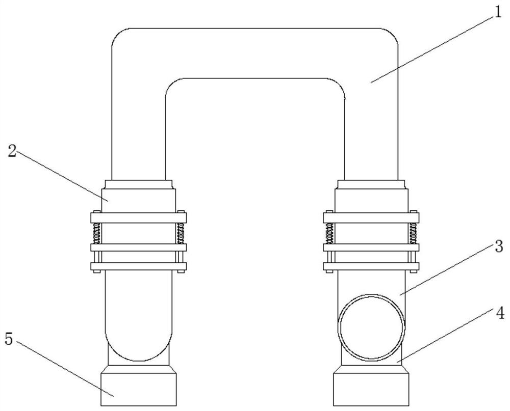
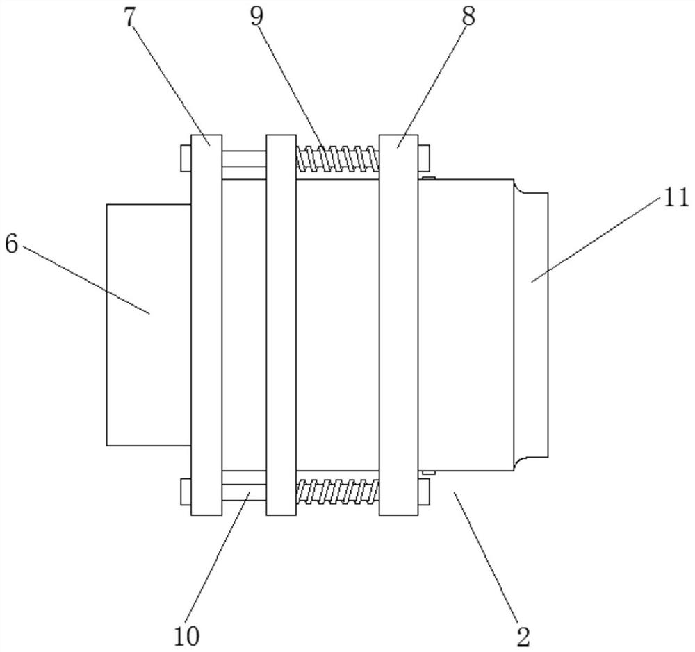
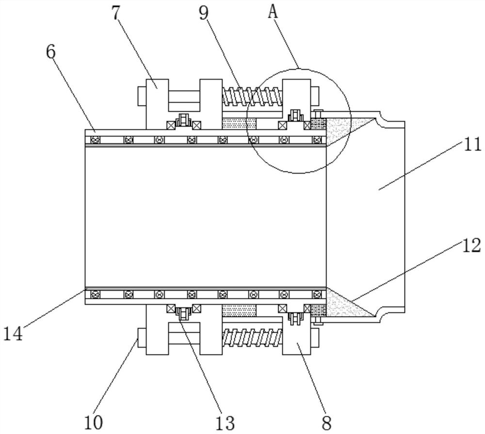
[0021] see Figure 1-5 , the present invention provides a technical solution:

[0022] A rotary compensator with flexible rotation and high pressure resistance, including a first pipeline 1, a rotary compensator 2, a second pipeline 3, a moving base 4, a fixed base 5 and a rotating sleeve 6, the two sides of the first pipeline 1 Each end is equipped with a rotary compensator 2, the rotary compensator 2 includes a rotary sleeve 6 and a seal seat 7, and the end...


PUM


Abstract

The present invention relates to a rotary compensator, especially a rotary compensator with flexible rotation and high pressure resistance, comprising a first pipeline, a rotary compensator, a second pipeline, a moving base, a fixed base and a rotating sleeve. The first Both ends of a pipeline are equipped with a rotary compensator, the rotary compensator includes a rotary sleeve and a sealing seat, and the end of the rotary sleeve close to the sealing seat is placed inside the rotary sleeve, and the interior of the rotary sleeve is provided with The inner cylinder, the reinforcing rib is fixedly installed between the inner cylinder and the rotating sleeve, the end of the sealing seat away from the rotating sleeve is installed through a small head, and a sealing block is arranged between the small head and the rotating sleeve , the sealing seat is covered with a sealing gland, and a seal is installed between the sealing gland and the rotating sleeve, and the sealing gland, the sealing block, the sealing seat and the rotating sleeve are enclosed A sealed cavity is provided, and the overall device of the present invention has simple structure, good rotation flexibility, and has a certain popularization effect.

Description

technical field [0001] The invention relates to a rotary compensator, in particular to a rotary compensator with flexible rotation and high pressure resistance. Background technique [0002] With the development of urban industry, thermal pipelines and petrochemical pipelines are also being updated day by day. Especially in recent years, many long-distance compensation pipelines and three-dimensional pipelines have appeared. Especially in the space pipe network, it is very difficult or even impossible to set up the fixed bracket, which seriously affects the design and development of the pipe network. At this time, it is necessary to use an injection-filled rotary compensator, which absorbs heat by its rotation. The thermal displacement of the pipeline plays the role of thermal compensation. At the same time, it consists of a rotating cylinder, a gland flange, a spring, a fastening flange, a guide slip ring, a packing, a retaining ring, a limit ring, an outer sleeve, and a re...

Claims


Application Information

Patent Timeline
Patent Type & Authority Patents(China)
IPC IPC(8): F16L51/00F16L51/04F16L27/08F16L27/093
CPCF16L51/00F16L51/04F16L27/0849F16L27/093
Inventor 林美根
Owner 江苏恒昌波纹管有限公司
Why Eureka
Try Eureka