Sterilizing pot and sterilizing and drying control method of sterilizing pot

A drying control and sterilizing pot technology, applied in drying, sterilizing, drying machine and other directions, can solve the problems of easy scalding to users, users cannot choose, and steam is easy to scald to users, etc., so as to improve the safety of use, improve User experience, the effect of meeting the needs of use

Active Publication Date: 2021-01-08
BEAR ELECTRICAL APPLIANCE CO LTD +1
View PDF8 Cites 1 Cited by
  • Summary
  • Abstract
  • Description
  • Claims
  • Application Information

AI Technical Summary

Problems solved by technology

Existing feeding bottle sterilizers generally only have a fixed wind speed gear, and users cannot select the gear according to their own needs; in addition, due to the non-independent control of the fan and the PTC heating element in the drying operation of the prior art, the two Either work at the same time or stop at the same time. After the drying operation is over, the disinfection chamber is in a high temperature state when the user opens the sterilizer, which is easy to burn the user, and there is a certain danger; similar problems exist in disinfection. After the disinfection is completed, the user opens the sterilizer. The disinfection chamber is in a high temperature state when the pot is in the pot, and the steam is easy to scald the user, posing a potential safety risk

Method used


Image

  • Sterilizing pot and sterilizing and drying control method of sterilizing pot
  • Sterilizing pot and sterilizing and drying control method of sterilizing pot
  • Sterilizing pot and sterilizing and drying control method of sterilizing pot

Examples


Embodiment Construction

[0026] In order to further explain the technical means and functions adopted by this application to achieve the predetermined purpose, the specific implementation, structure, features and functions according to this application will be described in detail below in conjunction with the drawings and preferred embodiments. In the following description, different "one embodiment" or "embodiment" do not necessarily refer to the same embodiment. Furthermore, the particular features, structures, or characteristics of one or more embodiments may be combined in any suitable manner.

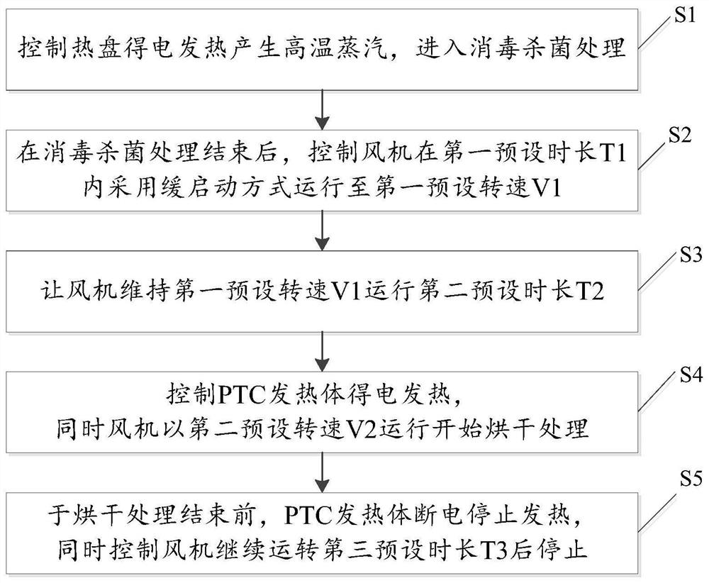
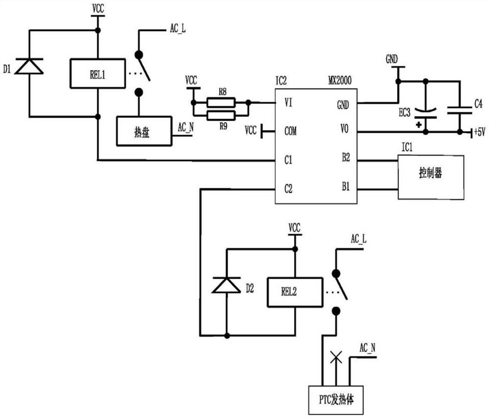
[0027] Such as figure 1 As shown, the sterilizer comprises a base 1, a base upper cover 2 fixed on the base 1 and a main housing 3 with a flip cover 31, the main housing 3 is fixed on the base upper cover 2, and the main housing 3 is connected with the base The cover 2 jointly forms a disinfection chamber for disinfection and drying; the base upper cover 2 is provided with a hot plate 21 (generally, an el...


PUM


Abstract

The invention discloses a sterilizing pot and a sterilizing and drying control method of the sterilizing pot. The sterilizing and drying control method comprises the following steps that a control panel controls a hot plate to be electrified for sterilization and disinfection; after the sterilization and disinfection are finished, the control panel controls a fan to operate to a first preset rotating speed V1 in a slow starting mode within a first preset time period; the control panel controls a PTC heating body to be electrified so as to heat air flow blown by the fan into hot air flow, and meanwhile, the control panel controls the fan to operate at a second preset rotating speed V2 so as to blow hot air formed into a sterilizing cavity for drying, wherein V2 is greater than or equal to V1 but less than or equal to V0; and the sterilizing pot is provided with a multi-stage gear switch, the multi-stage gear switch is respectively associated with different rotating speeds of the fan, and the second preset rotating speed V2 of the fan is determined by a user through the gear switch. The fan and the PTC heating body are independently controlled, the fan is started slowly, and the rotating speed is adjustable, so that the use safety and the use experience of the user are improved.

Description

technical field [0001] The invention relates to the technical field of household appliances, in particular to a sterilizer and a method for controlling disinfection and drying of the sterilizer. Background technique [0002] This section only provides background information related to the application to facilitate those skilled in the art to understand the application more thoroughly and accurately, and it is not necessarily the prior art. [0003] The main sterilization methods existing in the field of household appliances are high temperature, ultraviolet rays or ozone, each of which has advantages and disadvantages and has different usage occasions. [0004] Take the existing baby bottle sterilizer or sterilizer on the market as an example, which generally have the functions of high-temperature disinfection and drying. The drying generally uses a fan and a heating element to work at the same time, and blows out high-temperature hot air to dry the inside of the baby bottle...

Claims


Application Information

Patent Timeline
IPC IPC(8): F26B21/00F26B21/12A61L2/07A61L2/24A61L2/26
CPCF26B21/001F26B21/004F26B21/12A61L2/07A61L2/24A61L2/26A61L2202/14
Inventor 李一峰郑松杰
Owner BEAR ELECTRICAL APPLIANCE CO LTD
Why Eureka
Try Eureka