Pipe bending and die clamping device

A technology of clamping and bending pipes, applied in metal processing equipment, forming tools, manufacturing tools, etc., can solve the problems affecting the structural strength of pipe fittings, wrinkles, large stress concentration of pipe fittings, etc., to ensure the appearance and structural strength, to avoid wrinkles fold effect

Inactive Publication Date: 2021-01-12
REXON IND CORP LTD
View PDF7 Cites 0 Cited by
  • Summary
  • Abstract
  • Description
  • Claims
  • Application Information

AI Technical Summary

Problems solved by technology

[0003] When the above-mentioned pipe bending clamping device bends a pipe fitting (not shown in the figure), due to the high rigidity of the movable clamping mold 3, a relatively large stress concentration phenomenon occurs on the inner edge of the pipe fitting, and Wrinkles will occur, which will not only affect the appearance of the pipe fittings, but also affect the structural strength of the pipe fittings

Method used


Image

  • Pipe bending and die clamping device
  • Pipe bending and die clamping device
  • Pipe bending and die clamping device

Examples


Embodiment Construction

[0019] Below in conjunction with accompanying drawing and embodiment the present invention is described in detail:

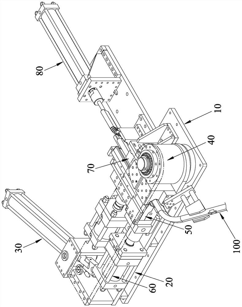
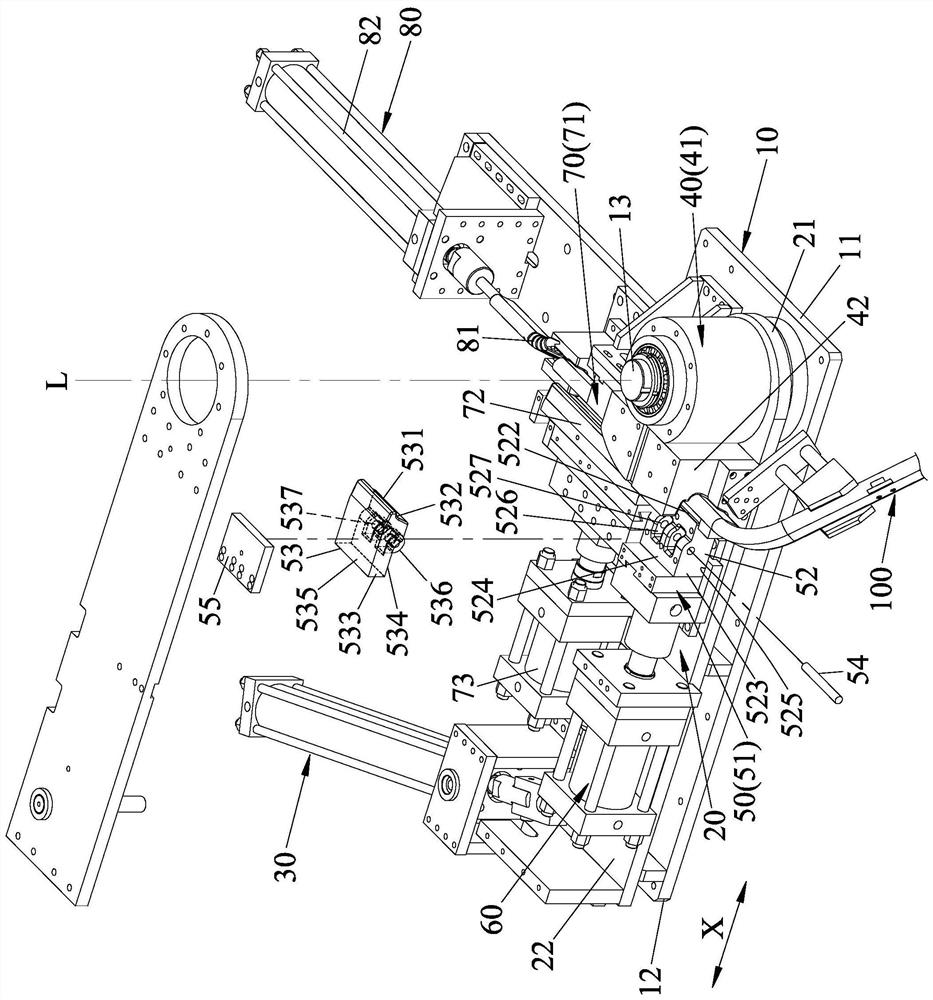
[0020] refer to figure 2 and image 3 , an embodiment of the bending pipe clamping device of the present invention, comprising a base 10, a bending pipe arm 20, a bending pipe driving member 30, a main mold unit 40, a clamping mold unit 50, and a clamping mold driving member 60 , a guide mold unit 70 and a core mold unit 80 .

[0021] The base 10 is plate-shaped and includes a first end 11, a second end 12 opposite to the first end 11 along a transverse axis X, and a The shaft 13 extends transversely to the axis L of the X axis.

[0022] The elbow arm 20 includes a pivot end 21 pivoted on the shaft 13 , and a driving end 22 opposite to the pivot 21 .

[0023] The pipe bending driver 30 is installed on the base 10 and can drive the driving end 22 of the pipe bending arm 20 to rotate around the axis L relative to the base 10 . The bending pipe driving member...


PUM


Abstract

The invention discloses a pipe bending and die clamping device. The device comprises a base, a pipe bending arm, a pipe bending driving piece, a main die unit, a die clamping unit and a die clamping driving piece. The main die unit comprises a main die wheel and an inner die clamping piece fixed to the main die wheel, and the die clamping unit is provided with a positioning base, a fixed die clamping piece and a movable die clamping piece. Due to the fact that the movable die clamping piece can pivot relative to the fixed die clamping piece, deformation space of a bent part of a pipe fitting can be provided during pipe bending operation, and the inner side edge of the bent part of the pipe fitting can be prevented from wrinkling.

Description

technical field [0001] The invention relates to a pipe bending device, in particular to a pipe bending clamping device. Background technique [0002] refer to figure 1 , there is an existing clamping device for bending pipes, which includes a main mold wheel 1, a fixed clamping mold 2 fixed to the main mold wheel 1, and a movable clamping mold that can be moved against or away from the fixed clamping mold 2 3. When the pipe bending operation is to be performed, the movable clamping die 3 leans against the fixed clamping die 2, and a bending die driver is used to drive a pipe bending arm (not shown in the figure) to drive the movable clamping die 3 and the fixed clamping die 2 and the main die wheel 1 rotate relative to a machine platform (not shown in the figure), and the pipe bending purpose can be achieved. [0003] When the above-mentioned pipe bending clamping device bends a pipe fitting (not shown in the figure), due to the high rigidity of the movable clamping mold ...

Claims


Application Information

Patent Timeline
Patent Type & Authority Applications(China)
IPC IPC(8): B21D37/10B21D9/05
CPCB21D37/10B21D9/05
Inventor 陈柏仰
Owner REXON IND CORP LTD
Why Eureka
Try Eureka