Cutting equipment for printing

A cutting and equipment technology, applied in the field of printing cutting equipment, can solve problems affecting the quality of material cutting, and achieve the effect of avoiding re-pollution and dyeing

Inactive Publication Date: 2021-01-12
刘文宏
View PDF0 Cites 0 Cited by
  • Summary
  • Abstract
  • Description
  • Claims
  • Application Information

AI Technical Summary

Problems solved by technology

[0003] When the existing printing and cutting equipment is cutting, the dye on the printed material is easy to be stained on the blade, and it is easy to

Method used


Image

  • Cutting equipment for printing
  • Cutting equipment for printing
  • Cutting equipment for printing

Examples


Example Embodiment

[0027] Example 1

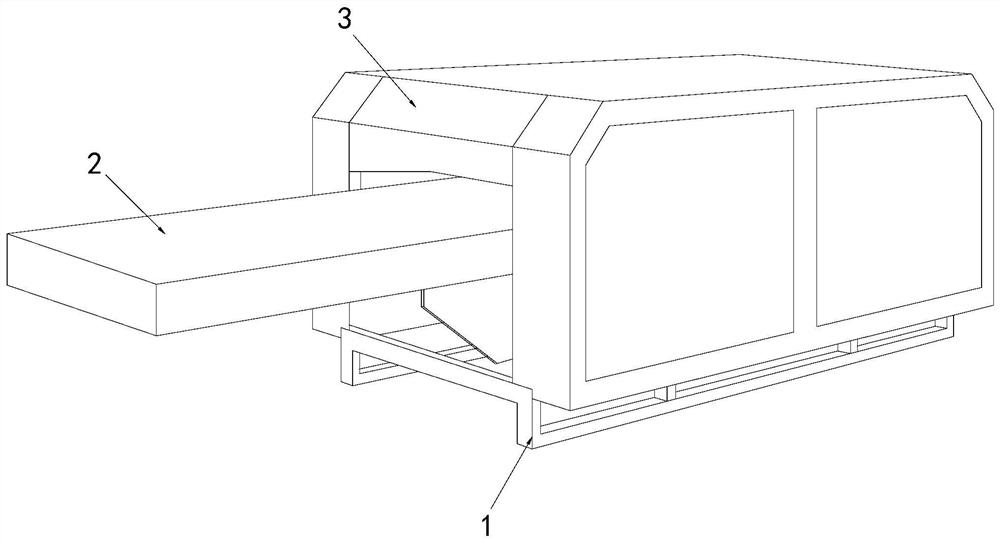
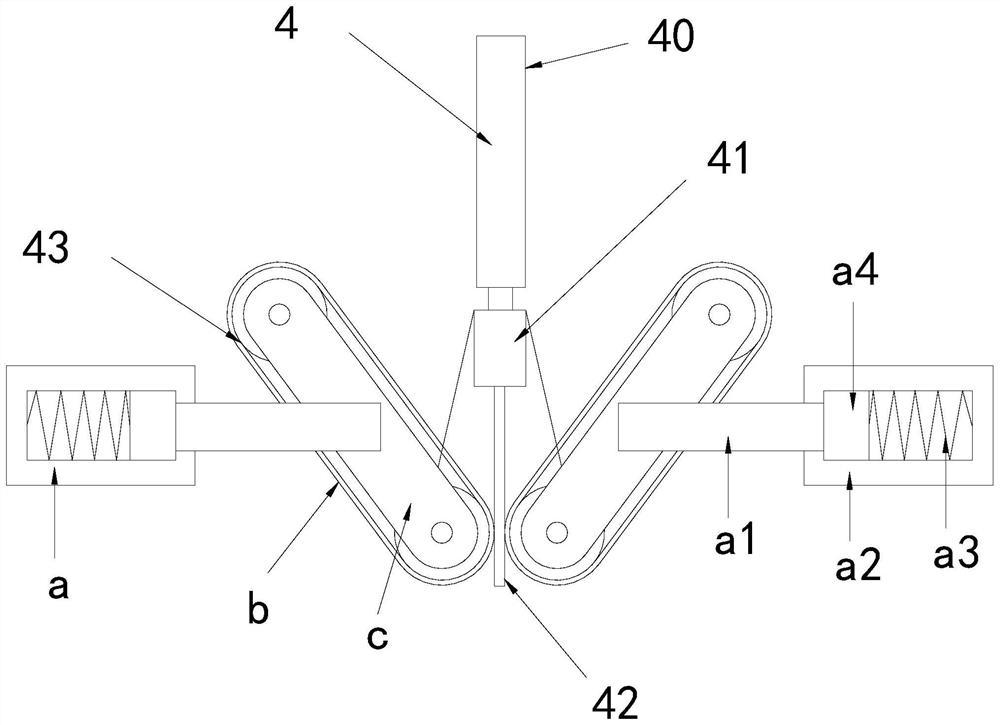
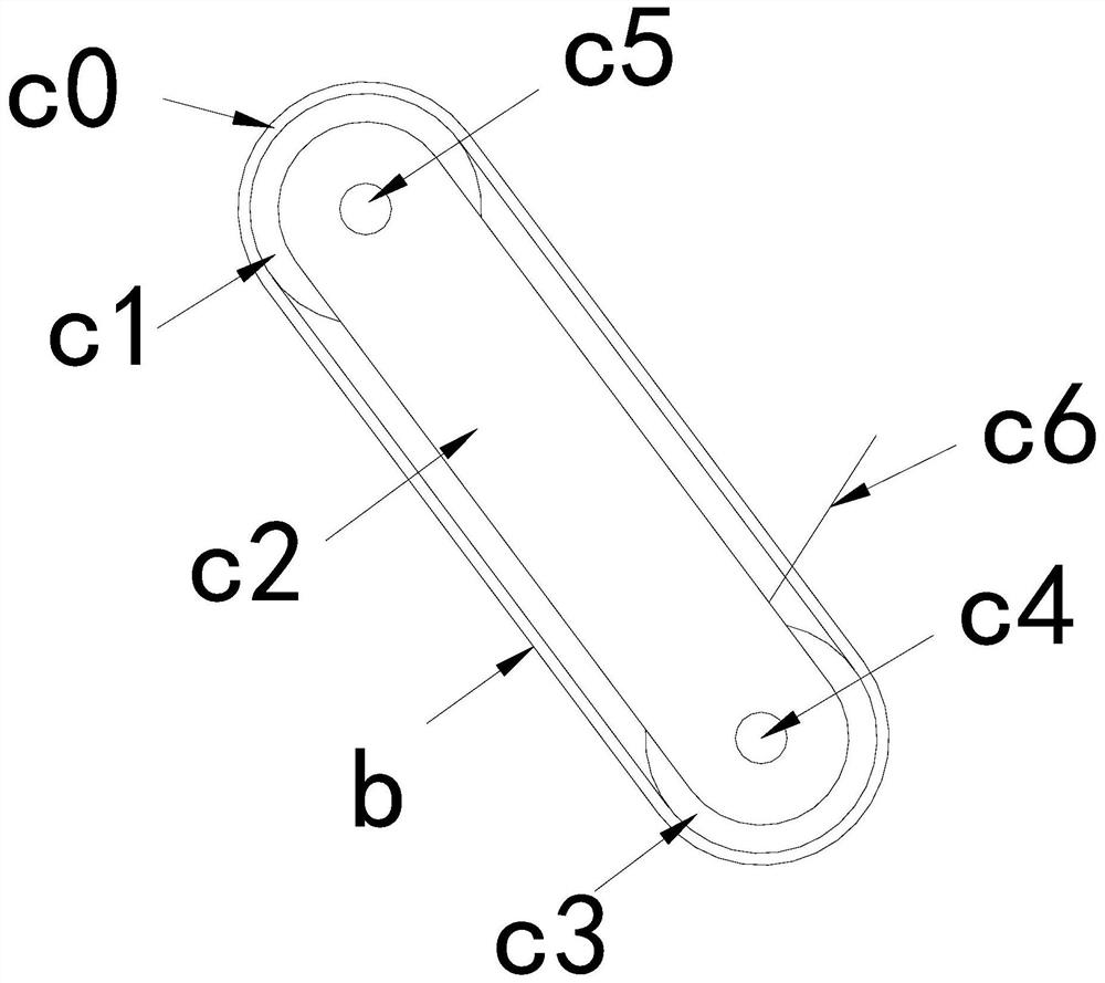
[0028] see Figure 1-3 , the present invention provides a technical solution for printing cutting equipment: its structure includes a bottom bracket 1, a conveying platform 2, and a body 3, the bottom of the body 3 is welded with a bracket 1, and the front of the body 3 is provided with a conveying platform 2, The inside of the body 3 is provided with a cutting device 4. The cutting device 4 includes a telescopic cylinder 40, a knife rest 41, a blade 42, and a wiping structure 43. The bottom of the telescopic cylinder 40 is connected with the knife rest 41. The knife A blade 42 is installed on the bottom of the frame 41, and the two sides of the blade 42 are respectively provided with a wiping structure 43, and the wiping structure 43 includes a moving structure a, a wiping cloth b, and a transmission structure c, and the moving structure a is connected with the transmission structure c , the transmission structure c is provided with a wiping cloth b, the w...

Example Embodiment

[0030] Example 2

[0031] see Figure 1-6 , the present invention provides a technical solution for printing cutting equipment: its structure includes a bottom bracket 1, a conveying platform 2, and a body 3, the bottom of the body 3 is welded with a bracket 1, and the front of the body 3 is provided with a conveying platform 2, so The inside of the body 3 is provided with a cutting device 4, the cutting device 4 includes a telescopic cylinder 40, a knife rest 41, a blade 42, a wiping structure 43, the bottom of the telescopic cylinder 40 is connected with the knife rest 41, and the knife rest The bottom of 41 is equipped with a blade 42, and the two sides of the blade 42 are respectively provided with a wiping structure 43, the wiping structure 43 includes a moving structure a, a wiping cloth b, and a transmission structure c, and the moving structure a is connected to the transmission structure c, The transmission structure c is provided with a wiping cloth b, and the wipin...


PUM


Abstract

The invention discloses cutting equipment for printing. The cutting equipment structurally comprises a bottom support, a conveying table and a machine body, wherein the support is welded to the bottomof the machine body, and the conveying table is arranged in front of the machine body. A cutting device is arranged in the machine body and comprises a telescopic cylinder, a knife rest, a blade andwiping structures, and the bottom of the telescopic cylinder is connected with the knife rest. The blade is arranged at the bottom of the knife rest, and the wiping structures are arranged on the twosides of the blade respectively. Each wiping structure comprises a moving structure, wiping cloth and a transmission structure, the moving structure is connected with the transmission structure, and the wiping cloth is arranged on the transmission structure and is in contact with the blade. The cutting equipment has the beneficial effects that the blade is wiped to keep clean to prevent from dyeing materials; and the position of the wiping cloth making contact with the blade is changed through transmission, and a new position is provided for wiping, so that secondary pollution is avoided.

Description

technical field [0001] The invention relates to the field of printing equipment, in particular to a cutting equipment for printing. Background technique [0002] Printing is a technology that transfers the ink to the surface of paper, fabric, leather and other materials through plate-making, ink application, pressurization and other processes to copy the content of the original manuscript in batches. After printing on the paper, it needs to Cut it to give the paper the desired shape. [0003] When the existing printing and cutting equipment is cutting, the dye on the printed material is easy to be stained on the blade, and it is easy to be stained on the material when the blade is next cut, resulting in different dyes on the material, which affects the quality of material cutting. quality. Contents of the invention [0004] The main purpose of the present invention is to overcome the deficiencies of the prior art and provide a cutting device for printing. [0005] The p...

Claims


Application Information

Patent Timeline
IPC IPC(8): B26D7/08B26D1/08
CPCB26D1/08B26D7/088
Inventor 刘文宏
Owner 刘文宏
Why Eureka
Try Eureka