Trademark pad printing machine for earphone round cover

A technology for pad printing machines and trademarks, which is applied to printing, printing machines, conveyor objects, etc., and can solve problems such as paint sticking to other parts of the earphone, inconvenient operation, and complicated structure

Inactive Publication Date: 2021-01-12
许从平
View PDF15 Cites 6 Cited by
  • Summary
  • Abstract
  • Description
  • Claims
  • Application Information

AI Technical Summary

Problems solved by technology

[0005] In order to overcome the disadvantages of the existing technology that the structure is complex and inconvenient for people to operate and that the paint is easily stained on other parts of the earphone, the technical problem of the present invention is: to provide a simple to operate and not easy to stain the paint on other parts of the earphone during printing. Logo pad printing machine for earphone dome cover

Method used


Image

  • Trademark pad printing machine for earphone round cover
  • Trademark pad printing machine for earphone round cover
  • Trademark pad printing machine for earphone round cover

Examples


Embodiment 1

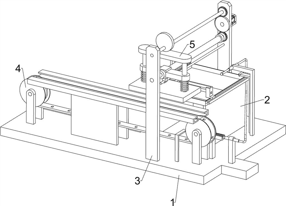
[0023] A trademark pad printing machine for earphone domes, such as figure 1 , figure 2 and image 3 As shown, it includes a base plate 1, a workbench 2, a first bearing seat 3, a transmission mechanism 4 and a pad printing mechanism 5. The workbench 2 is arranged on the right side of the top of the base plate 1, and the left and right sides of the top of the base plate 1 are fixedly connected with a first The bearing seat 3 is provided with a transmission mechanism 4 on the top left side of the bottom plate 1 , and a pad printing mechanism 5 is provided between the first bearing seat 3 .

[0024] When people need to use this machine, first people insert the earphone into the transfer mechanism 4, then place the pigment required for printing on the pad printing mechanism 5, then manually rotate the transfer mechanism 4, and start the pad printing mechanism 5 to operate, and wait for the earphone When moving to the bottom of the pad printing mechanism 5, people can stop rota...

Embodiment 2

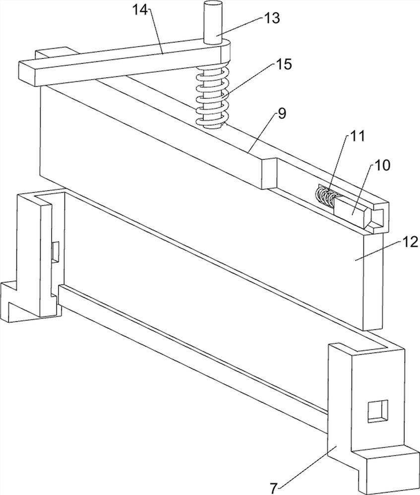
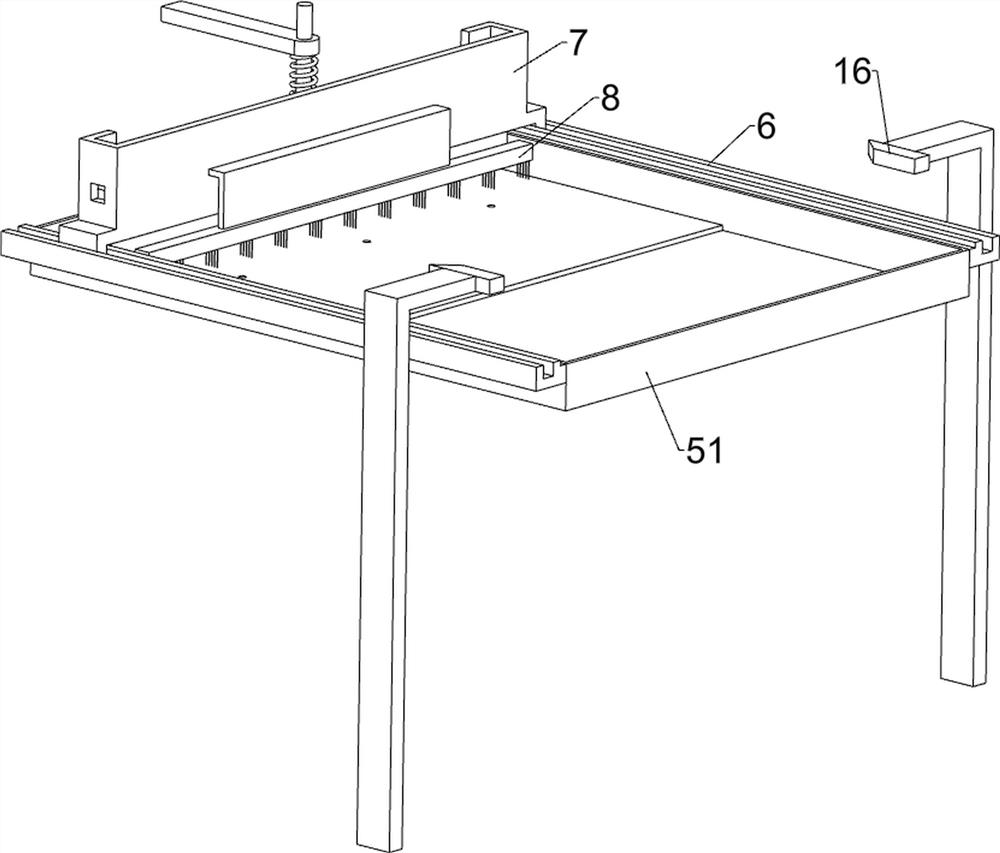
[0030] On the basis of Example 1, such as Figure 4 , Figure 5 and Figure 6 As shown, it also includes a second slide rail 6, a first slide block 7, a brush 8, a movable plate 9, a wedge block 10, a second elastic member 11, a scraper 12, a connecting rod 13, a second slide block 14, a first Three elastic members 15 and L-shaped blocks 16, the top of the discharge frame 51 is symmetrically provided with the second slide rail 6, between the second slide rail 6 is provided with the first slide block 7 in a sliding manner, on the first slide block 7 Front and rear symmetry are provided with square grooves, first slide block 7 right side is provided with brush 8, is provided with movable plate 9 slidingly on first slide block 7, is provided with wedge-shaped block 10 in sliding type at both ends of movable plate 9, wedge-shaped block 10 and the movable plate 9 are provided with a second elastic member 11, the second elastic member 11 is a compression spring, the bottom of the ...


PUM


Abstract

The invention relates to a pad printing machine, in particular to a trademark pad printing machine for an earphone round cover. The trademark pad printing machine for the earphone round cover providedby the invention is easy to operate, and pigment is not prone to staining other parts of an earphone in the printing process. The trademark pad printing machine for the earphone round cover comprisesa bottom plate, first bearing bases, a conveying mechanism, a pad printing mechanism, wherein a workbench is arranged at the top of the bottom plate; the first bearing bases are symmetrically arranged on the side, close to the workbench, of the top of the bottom plate; the conveying mechanism is arranged at the top of the bottom plate; and the pad printing mechanism is arranged between the firstbearing bases. By starting a servo motor, rotation of a second rotating shaft is achieved; and then through cooperation of the conveying mechanism and the pad printing mechanism, when the earphone moves to the position below the pad printing mechanism, the pad printing mechanism prints a trademark on the earphone, and the position of the trademark on the earphone is consistent.

Description

technical field [0001] The invention relates to a pad printing machine, in particular to a trademark pad printing machine for earphone round covers. Background technique [0002] In-ear earphones, also known as ear canal earphones and in-ear earplugs, are earphones used inside the human auditory organ. According to their design, they will seal the user's ear canal during use. Due to their small size, convenience and perfect Excellent sound insulation effect, in-ear headphones are very popular. [0003] Since there are many brands of in-ear earphones, when making earphones, trademarks are usually printed on the earphones. Compared with manual printing, it is more efficient to use a printing device to print trademarks on the earphones, but the existing printing device , the general structure is complex, and it is not convenient for people to operate, and when the earphone is printed, it is easy to make other parts of the earphone be stained with paint, and then affect the app...

Claims


Application Information

Patent Timeline
Patent Type & Authority Applications(China)
IPC IPC(8): B41F17/00B41F21/00B41F31/02B41F31/04B65G47/82
CPCB41F17/001B41F21/00B41F31/02B41F31/04B65G47/82
Inventor 许从平
Owner 许从平
Why Eureka
Try Eureka