
Micro-vibration type constant-humidity incubator

A micro-vibration, incubator technology, applied in enzymology/microbiology devices, biochemical instruments, biochemical equipment and methods, etc., can solve problems such as affecting the normal culture of microorganisms, and achieve good results and uniform heat distribution.

Active Publication Date: 2021-01-12
太仓艺斯高医疗器械科技有限公司
View PDF6 Cites 1 Cited by
  • Summary
  • Abstract
  • Description
  • Claims
  • Application Information

AI Technical Summary

Problems solved by technology

[0005] The purpose of the present invention is to provide a micro-vibration constant-humidity incubator that can effectively guarantee the growth environment of microorganisms in order to solve the problem that most traditional incubators easily affect the normal cultivation of microorganisms in the process of processing condensed water

Method used


Image

  • Micro-vibration type constant-humidity incubator
  • Micro-vibration type constant-humidity incubator
  • Micro-vibration type constant-humidity incubator

Examples


Embodiment 1

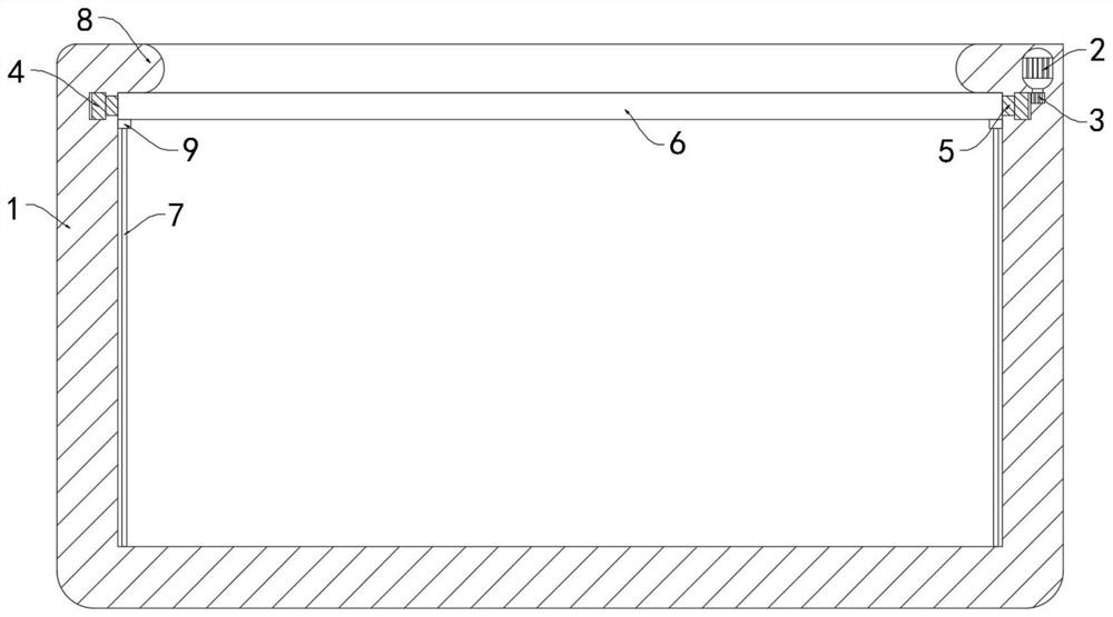
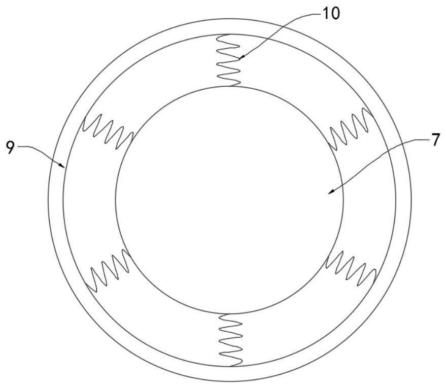
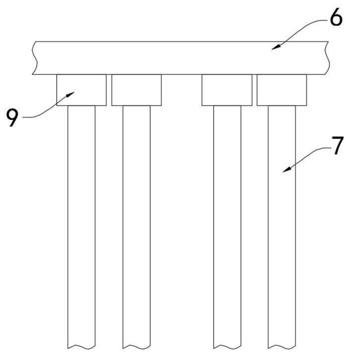
[0025] like Figure 1-3 As shown, a micro-vibration constant-humidity constant temperature box includes a box body 1, a power supply and a micro-motor 2. It is worth mentioning that the upper edge of the box body 1 extends inward along its radial direction to form a protective ring 8. The protective ring 8 can play a protective role to the rotating ring 6 below it.

[0026] The power supply is connected with a frequency conversion module, and the frequency conversion module will continuously change the direction of the current. The micro motor 2 is fixedly installed in the side wall of the box body 1. The output end of the micro motor 2 is fixedly connected to the gear 3, and the box body 1 is embedded with an outer gear ring 4. , the outer gear ring 4 is rotatably connected with the side wall of the box body 1, the outer gear ring 4 is meshed with the gear 3, the inner ring side wall of the outer gear ring 4 is fixedly connected with a connecting ring 5, and the connecting ri...

Embodiment 2

[0033] like Figure 4 As shown, the difference between this embodiment and Embodiment 1 is that: the lower side wall of the external gear ring 4 is fixedly connected with a drum 11, the drum 11 is connected with the side wall of the box body 1 in rotation, and the inner surface of the box body 1 is fixedly embedded A temperature-conducting layer 12 is provided, and the side wall of the box body 1 between the drum 11 and the temperature-conducting layer 12 is a friction heating layer 13 .

[0034] The capillary strip 7 includes an insulating tube 14, and a plurality of conductive strips 15 are fixedly connected in the insulating tube 14, and a liquid storage tank 16 communicating with the outside is formed between every two conductive strips 15.

[0035] In this embodiment, when the outer gear ring 4 rotates with the gear 3, it will drive the drum 11 to rotate, and the rotating drum 11 will be driven to rub against the friction heating layer 13 to generate heat, and the generat...


PUM


Abstract

The invention belongs to the field of biological culture, and particularly relates to a micro-vibration type constant-humidity incubator. The incubator comprises a box body, a power supply and a micromotor, wherein the power supply is connected with a frequency conversion module; the micro motor is fixedly installed in the side wall of the box body; the output end of the micro motor is fixedly connected with a gear; an outer gear ring is embedded in the box body; the outer gear ring is rotationally connected with the side wall of the box body; the outer gear ring is in engaged connection withthe gear; the side wall of an inner ring of the outer gear ring is fixedly connected with a connecting ring; the connecting ring extends into an inner cavity of the box body; and the side wall of aninner ring of the connecting ring is fixedly connected with a rotating ring. According to the invention, by arranging a rotary drum and a friction heating layer, the outer gear ring can drive the rotary drum to rotate when rotating along with the gear, the rotary drum which rotates can be driven to rub with the friction heating layer to generate heat, the generated heat can be conducted to the interior of the box body through a temperature conduction layer, and the inner side wall of the whole box body is heated, so that the influence of non-uniform heating on microorganism growth can be effectively avoided.

Description

technical field [0001] The invention belongs to the field of biological cultivation, in particular to a micro-vibration constant-humidity incubator. Background technique [0002] The incubator is a box-shaped appliance used to raise or cultivate organisms or a part of organisms (cells, etc.) at a certain temperature. Stringent requirements. [0003] The sealing of the incubator is generally good. During the process of cultivating microorganisms, the temperature inside the box is relatively high, and the temperature difference between the inside and outside of the box is likely to cause water droplets to condense on the inner wall of the box. Most of the traditional treatment methods are to pass through the incubator The flowing gas will blow out the water in the box, but the loss of water will reduce the air humidity in the box. The growth conditions of microorganisms are generally strict, and the change of humidity will greatly affect the normal progress of microbial culti...

Claims


Application Information

Patent Timeline
Patent Type & Authority Applications(China)
IPC IPC(8): C12M1/00C12M1/38C12M1/36
CPCC12M23/02C12M41/22C12M41/34
Inventor 方莹峰
Owner 太仓艺斯高医疗器械科技有限公司
Learn More