High-pressure-resistant fluid control equipment

A control equipment, high-pressure technology, applied in mechanical equipment, cocks including cut-off devices, valve operation/release devices, etc., to achieve the effect of firm overall structure and good pressure resistance of the valve body

Pending Publication Date: 2021-01-12
苏州特思克流体控制设备有限公司
View PDF8 Cites 0 Cited by
  • Summary
  • Abstract
  • Description
  • Claims
  • Application Information

AI Technical Summary

Problems solved by technology

[0003] Although this traditional ball valve can control the fluid, it can only be applied to some more conventional fluid delivery pipelines. Now many high-pressure fluid delivery pipelines urgently need to provide a ball valve that can withstand high pressure.

Method used


Image

  • High-pressure-resistant fluid control equipment
  • High-pressure-resistant fluid control equipment
  • High-pressure-resistant fluid control equipment

Examples


Embodiment

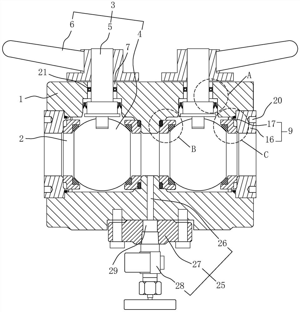
[0036] refer to figure 1 , a high-pressure resistant fluid control device, including a valve body 1, a valve chamber 2 set on the valve body 1, and a flow rate control assembly 3. The valve body 1 is generally cylindrical in shape, and the flow rate control assembly 3 is along the length direction of the valve body 1. The symmetrical setup has two groups. The flow rate control assembly 3 includes a valve ball 4, a valve stem 5 and a handle 6 that are rotatably arranged in the valve chamber 2. The valve body 1 is provided with a shaft-through hole 7 communicating with the valve chamber 2, and the valve stem 5 passes through the shaft-through hole. 7 is connected with the valve ball 4, and the handle 6 is welded on the valve stem 5. By holding the handle 6, the valve stem 5 can be rotated conveniently, and then the valve ball 4 is driven to rotate, so as to control the delivery efficiency of the fluid in the valve chamber 2.

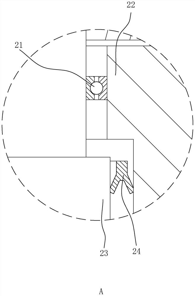
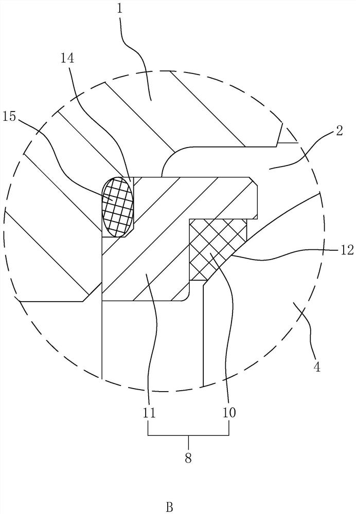
[0037] refer to figure 1 and figure 2 , the valv...


PUM


Abstract

The invention discloses high-pressure-resistant fluid control equipment, and is applied to the field of valves. According to the technical scheme, the equipment is characterized by comprising a valvebody, a valve cavity and flow speed control assemblies, wherein the valve cavity is formed in the valve body, the flow speed control assemblies are arranged in the valve cavity; the two flow speed control assemblies comprise valve balls rotationally arranged in the valve cavity, valve rods connected with the valve balls and handles arranged on the valve rods, shaft penetrating through holes communicating with the valve cavity are formed in the valve body, and the valve rods can pass through the shaft penetrating through holes; and a valve seat assembly used for sealing gaps between the valve balls and the valve body is arranged in the valve cavity, and valve deck assemblies used for limiting the positions of the valve balls are arranged at the two ends of the valve body. The high-pressure-resistant fluid control equipment has the technical effects that the high-pressure-resistant fluid control equipment can well bear high-pressure and even ultrahigh-pressure fluid pressure without leakage, so that a valve can better control fluid conveying in a pipeline.

Description

technical field [0001] The invention relates to the field of valves, in particular to a high-pressure-resistant fluid control device. Background technique [0002] At present, the Chinese invention patent with the notification number CN107387797B discloses a ball valve, including: a valve body with an inner cavity; a valve seat arranged in the inner cavity, and an accommodation space is formed between one end of the valve seat and the valve body; In the accommodating space, the spring abutment is arranged between the valve body and the valve seat; the ball valve also includes: an isolation cylinder, which is connected between the valve body and the valve seat, and separates the accommodating space into independent spring accommodating spaces and over-current space, the spring is accommodated in the spring accommodation space; the ball, the valve body is provided with a valve port communicating with the ball, the end surface of the valve seat in contact with the spring is pro...

Claims


Application Information

Patent Timeline
Patent Type & Authority Applications(China)
IPC IPC(8): F16K5/06F16K5/08F16K5/20F16K31/60F16K27/06
CPCF16K5/0684F16K5/0694F16K5/08F16K5/201F16K31/60F16K27/067
Inventor 吴磊张绍南
Owner 苏州特思克流体控制设备有限公司
Why Eureka
Try Eureka