Disc sampler for cloth detection

A disc sampling and cloth detection technology, applied in the sampling device and other directions, can solve the problems of unflattened, increased error, unfavorable cutting, etc., and achieves the effect of high accuracy, improved precision, convenient and accurate cutting

Inactive Publication Date: 2021-01-12
陈兴元
View PDF0 Cites 2 Cited by
  • Summary
  • Abstract
  • Description
  • Claims
  • Application Information

AI Technical Summary

Problems solved by technology

[0003] 1. When performing disk cutting and sampling, the sampling area is generally very small. Therefore, in order to ensure the accuracy of the results, it is necessary to ensure that the cloth is completely flattened before cutting, but in practice it is only Manually lay the disc sampler on it, and then start sampling, which will more or less cause local wrinkles or unflattened fabrics, which will cause inaccurate sampling areas and inaccurate results. Meet the actual requirements, the error is large;
[0004] 2. When the disc is cut, the cloth is pressed tightly by hand and then rotated, which will drive the pressing block to rotate when rotating, which will cause the cloth to wrinkle and twist. On the one hand, it will not It is good for cutting, because the fabric will produce offset wrinkles, etc. On the other hand, the unstable rotation of the fabric will also cause inaccurate cutting, further increasing the error

Method used


Image

  • Disc sampler for cloth detection
  • Disc sampler for cloth detection
  • Disc sampler for cloth detection

Examples


Embodiment Construction

[0021] The following will clearly and completely describe the technical solutions in the embodiments of the present invention with reference to the accompanying drawings in the embodiments of the present invention. Obviously, the described embodiments are only some, not all, embodiments of the present invention. Based on the embodiments of the present invention, all other embodiments obtained by persons of ordinary skill in the art without making creative efforts belong to the protection scope of the present invention.

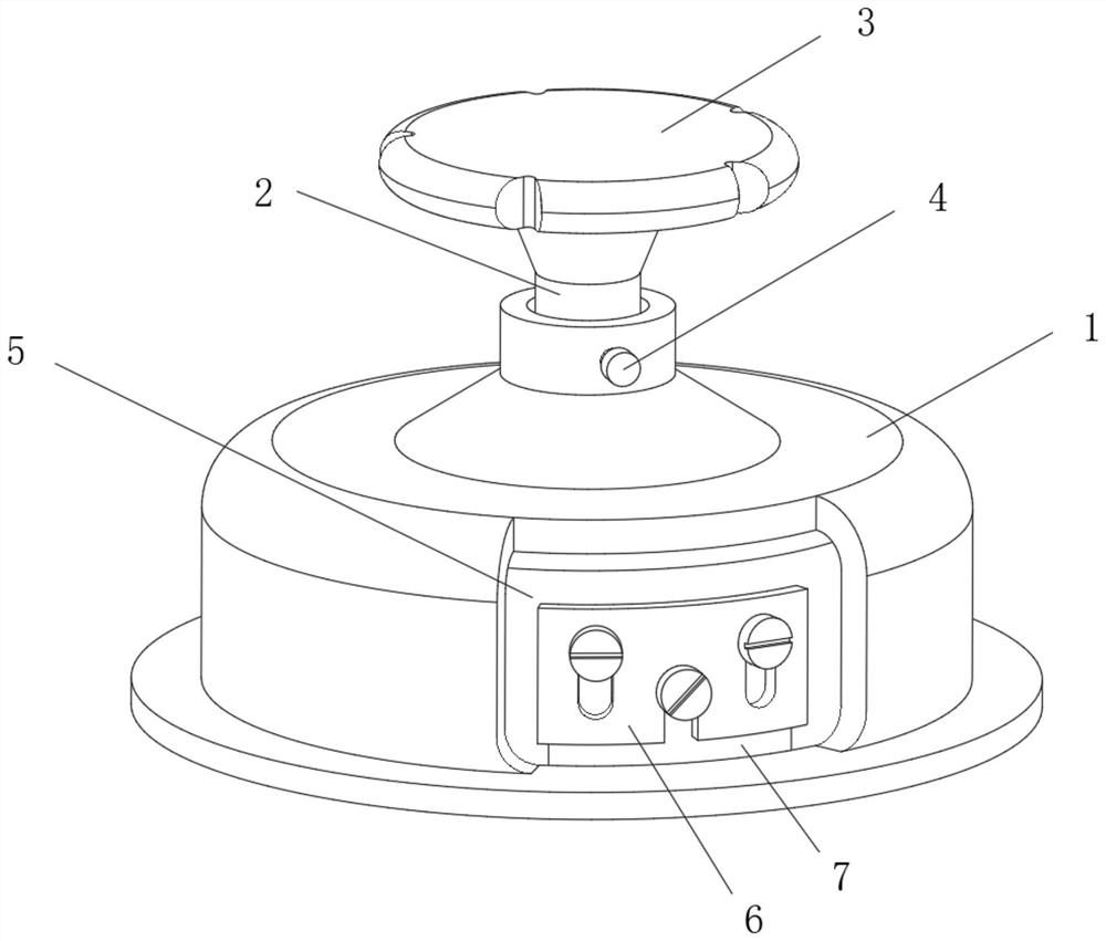
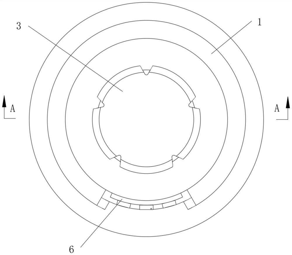
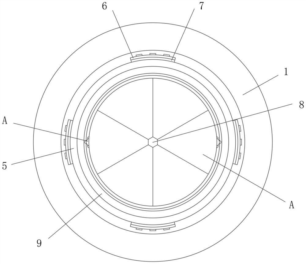
[0022] see Figure 1-6 , a disc sampler for cloth detection, comprising an outer shell 1, the middle part of the outer shell 1 is movably socketed with a rotating sleeve rod 2, and the top of the rotating sleeve rod 2 is fixedly equipped with an active turntable 3, and the top of the outer shell 1 is socketed and rotated The outer ring of the sleeve rod 2 is movably socketed with the limit bolt 4, and the inner part of the outer casing 1 is equipped with a cut...


PUM


Abstract

The invention relates to the technical field of cloth detection equipment, and discloses a disc sampler for cloth detection, which comprises an outer shell, the middle part of the outer shell is movably sleeved with a rotating sleeve rod, the top of the rotating sleeve rod is fixedly provided with a driving turntable, the outer shell is internally and movably provided with a cutter head, and the outer ring of the cutter head is fixedly provided with four cutter rests in a cross shape; the inner ring of the sleeve hole is movably sleeved with a middle shaft rod, the outer ring of the middle shaft rod is movably sleeved with a sleeve ring fixedly connected with the bottom of the rotating sleeve rod, the bottom of the sleeve ring is movably connected with a connecting rod, the bottom of the connecting rod is movably connected with a rolling shaft, and the interior of the cutter head is movably sleeved with an inner pressing disc, a tension spring is fixedly connected to the middle of theinner top of the inner pressing disc, a cloth pressing block is fixedly connected to the bottom of the tension spring, the bottom of the rolling shaft abuts against the middle of the top of the clothpressing block, and the disc sampler guarantees the sampling precision and the good sampling effect through cooperative use of the cloth pressing block and the inner pressing disc.

Description

technical field [0001] The invention relates to the technical field of cloth detection equipment, in particular to a disc sampler for cloth detection. Background technique [0002] After the fabric is produced, quality testing is required. The conventional testing method is to use the method of sampling and testing. The disc sampler is used to take a certain area of ​​the fabric and carry out weighing and other tests. The principle of the disc sampler is simple, and the outer shell is used. and the internal pressing block to press the cloth, and then turn the cutter head with the blade on the outer ring to cut the cloth, and then detect the result according to the size and quality of the cut cloth, but in actual use, the existing disc sampler There are still some problems: [0003] 1. When performing disk cutting and sampling, the sampling area is generally very small. Therefore, in order to ensure the accuracy of the results, it is necessary to ensure that the cloth is com...

Claims


Application Information

Patent Timeline
Patent Type & Authority Applications(China)
IPC IPC(8): G01N1/04
CPCG01N1/04
Inventor 陈兴元
Owner 陈兴元
Why Eureka
Try Eureka