Automatic weld defect extraction method

An automatic extraction and defect technology, applied in image analysis, image enhancement, instruments, etc., can solve the problems such as the accuracy rate needs to be improved, the operation hardware requirements are increased, and the data volume requirements are too high, so as to reduce the number of images, reduce requirements, The effect of increasing usage

Pending Publication Date: 2021-01-12
SHANGHAI DIANJI UNIV
View PDF2 Cites 4 Cited by
  • Summary
  • Abstract
  • Description
  • Claims
  • Application Information

AI Technical Summary

Problems solved by technology

The CNN network uses a complex network structure to detect images, but its excessive data volume requirements and operating hardware requirements greatly increase the cost of use
The FCN network cancels the fully connected layer and can generate a prediction for each pixel, but the accuracy of the result needs to be improved

Method used


Image

  • Automatic weld defect extraction method
  • Automatic weld defect extraction method
  • Automatic weld defect extraction method

Examples


Embodiment Construction

[0038] In order to facilitate the understanding of the present application, the present application will be described more fully below with reference to the relevant drawings. A preferred embodiment of the application is shown in the drawings. However, the present application can be embodied in many different forms and is not limited to the embodiments described herein. On the contrary, the purpose of providing these embodiments is to make the disclosure of this application more thorough and comprehensive.

[0039] It should be noted that when an element is considered to be "connected" to another element, it may be directly connected to and integrally integrated with the other element, or there may be an intervening element at the same time. The terms "mounted", "one end", "the other end" and similar expressions are used herein for the purpose of description only.

[0040] Unless otherwise defined, all technical and scientific terms used herein have the same meaning as commo...


PUM


Abstract

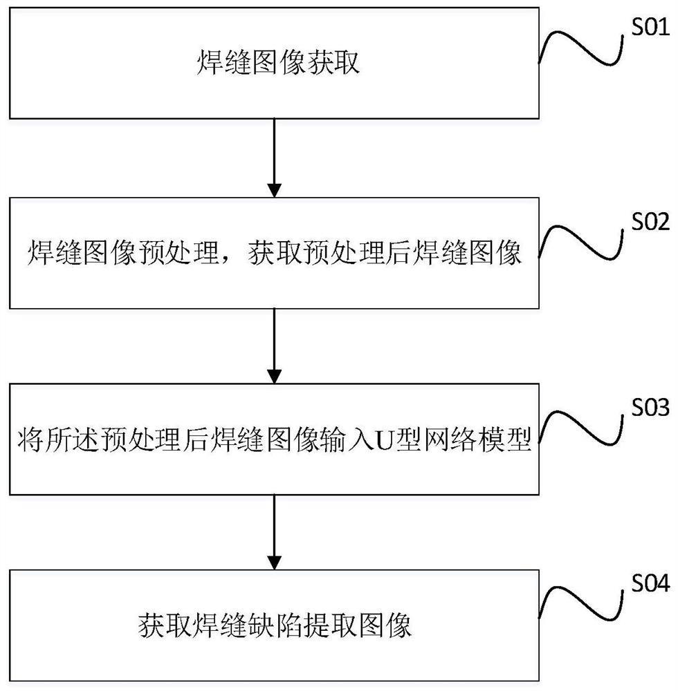
The invention discloses an automatic weld defect extraction method. The method comprises the following steps: acquiring a weld image; pre-processing the weld joint image to obtain a pre-processed weldjoint image; inputting the preprocessed weld joint image into a U-shaped network model, the U-shaped network model comprising a network input end, a network output end, a down-sampling part and an up-sampling part, the down-sampling part being composed of an encoder and ResNet34, the up-sampling part being composed of a decoder and Unet, and the up-sampling part being composed of a decoder and Unet, the upper sampling part and the lower sampling part being superposed by adopting jump connection, the network input end adopting a channel image adaptive to ResNet34 as an input image, the outputend being connected to the input end of the lower sampling part, and the output end of the upper sampling part being used for converting the image into a single-channel image and outputing the single-channel image; obtaining weld seam extraction images.

Description

technical field [0001] The invention relates to the field of welding seam detection methods, in particular to an automatic extraction method for X-ray pipeline welding seam defects. Background technique [0002] X-ray inspection is a very important method in the non-destructive testing of welds at this stage. It is widely used because of its penetrating and non-destructive characteristics, which can save money and time in troubleshooting and research. . At present, the results of X-ray inspection are generally evaluated manually, supplemented by computer evaluation. The evaluation process is very dependent on the personal ability of the evaluators, has strong subjectivity, and is easily influenced by the outside world, which will lead to problems such as wrong judgments and missed judgments to a certain extent. The current X-ray imaging technology has also increased the requirements for inspectors, especially after the digitization of X-ray film, there will be a series of ...

Claims


Application Information

Patent Timeline
Patent Type & Authority Applications(China)
IPC IPC(8): G06T7/90G06T7/13G06T3/40G06N3/04G06K9/62G01N23/04
CPCG06T7/90G06T7/13G06T3/4038G01N23/04G06T2207/30152G06N3/045G06F18/214
Inventor 丁哲浩陈田
Owner SHANGHAI DIANJI UNIV
Why Eureka
Try Eureka