Linear motor

A technology of linear motors and coils, applied in the direction of electromechanical devices, electrical components, electric components, etc., can solve the problems of low processing efficiency, low coil utilization rate, complex process, etc., and achieve the effect of improving utilization rate

Active Publication Date: 2021-01-12
HANS LASER TECH IND GRP CO LTD +1
View PDF6 Cites 0 Cited by
  • Summary
  • Abstract
  • Description
  • Claims
  • Application Information

AI Technical Summary

Problems solved by technology

[0003] refer to figure 1 , figure 1 It is a structural schematic diagram of a traditional linear motor. In a traditional linear motor, the enameled wire is wound into a coil 2 and then put on the core teeth 12 on the iron core 1. The process of assembling the coil 2 and the iron core 1 is relatively complicated, especially to provide For a high-thrust linear motor, set core teeth 12 on three sides of the iron core 1, and then put a coil 2 on each core tooth 12;
[0004] When several sides of the iron core 1 are provided with core teeth 12, for example figure 1 Core teeth 12 are provided on both sides of the middle, and coils 2 are sleeved on each core tooth 12 of the two sides. It can be seen that the number of coils 2 required is much larger than that of one side, so the processing The process is more cumbersome and time-consuming, the processing efficiency is low, and because only one side of a coil is used to generate thrust in this coil setting method, the utilization rate of the coil is very low

Method used


Image

  • Linear motor
  • Linear motor
  • Linear motor

Examples


Embodiment approach

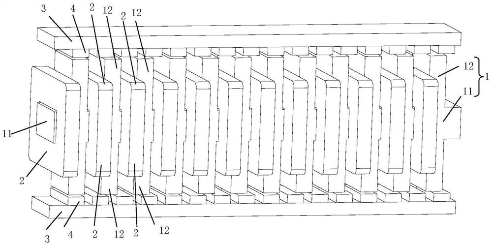
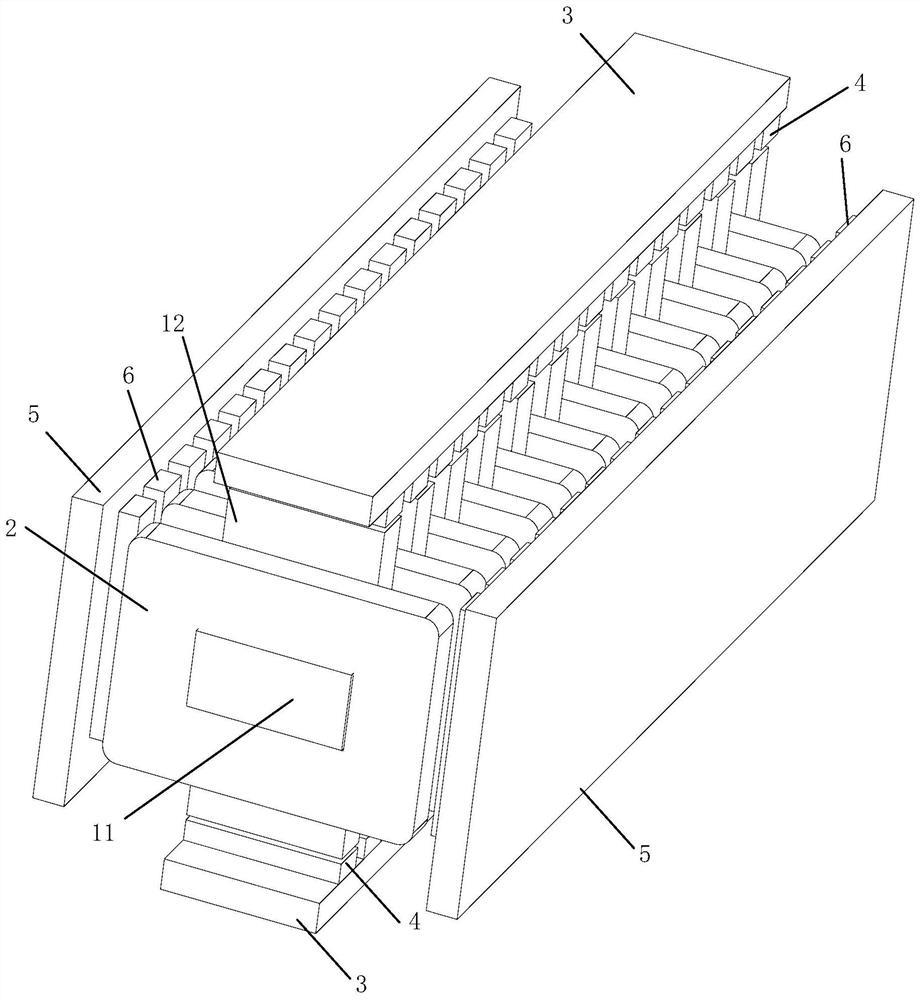
[0059] Optionally, in the first embodiment, one outer side surface of the iron core body 11 provided with the core teeth 12 is provided with the first magnetic conducting plate 3 , and the number of the first magnetic conducting plate 3 is one.

[0060] Optionally, in the first embodiment, the two outer sides of the core body 11 provided with the core teeth 12 are respectively provided with the first magnetic conductive plates 3, and the number of the first magnetic conductive plates 3 is two. indivual.

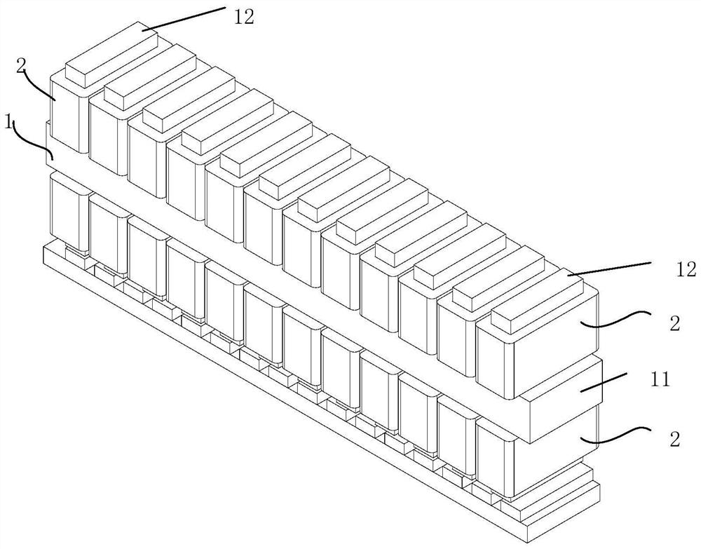
[0061] Specifically, in this embodiment, the iron core body 11 is a strip-shaped structure arranged along the movement direction of the linear motor. Among all the outer surfaces of the iron core body 11, the four surfaces along the length direction of the strip-shaped structure are called On the outer side, the two ends of the strip structure are called ends. The core teeth 12 are a plurality of protrusions protruding from the core body 11. The core teeth 12 are arranged in ...


PUM


Abstract

The invention discloses a linear motor. The motor comprises an iron core, a coil, a first concentrating flux plate and a first permanent magnet, wherein the iron core comprises an iron core body and core teeth which are arranged on at least one outer side face of the iron core body and protrude out of the iron core body. At least one of all the outer side faces, provided with the core teeth, of the iron core is provided with a first magnetic conductive plate, a first permanent magnet is arranged on the side, facing the core teeth, of the first magnetic conductive plate, one magnetic pole of the first permanent magnet is adjacent to the core teeth, and the magnetic pole ends, adjacent to the core teeth, of the first permanent magnet are arranged in the mode that N poles and S poles or S poles and N poles are alternately arranged. The coil is wound on the outer side face of the iron core body, and the winding direction of the coil is parallel to the protruding direction of the core teeth. Magnetic poles of a magnetic field generated by electrifying in the coil interact with magnetic poles, adjacent to the core teeth, of the corresponding first permanent magnets, and thrust is generated in the length direction of the iron core body to push the iron core or the first concentrating flux plate to move. The winding process of the coil is very simple, and the utilization rate of the coil can be improved.

Description

technical field [0001] The invention relates to the technical field of motors, in particular to a linear motor. Background technique [0002] Linear motors have been widely used in linear motor subways, maglev trains, linear motor machining centers, automated assembly lines, direct-drive elevators and many other application fields and occasions. [0003] see figure 1 , figure 1 It is a schematic diagram of the structure of a traditional linear motor. The traditional linear motor is to wind the enameled wire into a coil 2 and then cover it on the core teeth 12 on the iron core 1. The process of assembling the coil 2 and the iron core 1 is relatively complicated, especially in order to provide When the high-thrust linear motor is used, core teeth 12 are set on three sides of the iron core 1, and then each core tooth 12 is covered with a coil 2; [0004] When the core teeth 12 are provided on several sides of the iron core 1, for example figure 1 Core teeth 12 are provided ...

Claims


Application Information

Patent Timeline
Patent Type & Authority Applications(China)
IPC IPC(8): H02K41/03
CPCH02K41/031
Inventor 魏孔宇刘艳余何敏唐政高云峰
Owner HANS LASER TECH IND GRP CO LTD
Why Eureka
Try Eureka