

Hospital corridor positioning track hidden disinfection machine
A technology for positioning rails and disinfection machines, which is applied in disinfection, sanitary equipment for toilets, water supply devices, etc., can solve problems such as large spraying area, heavy burden on staff, and large water storage capacity, achieve large coverage area and reduce work intensity. , the effect of improving work efficiency
- Summary
- Abstract
- Description
- Claims
- Application Information
AI Technical Summary
Problems solved by technology
Method used
Image


Examples
Embodiment 1
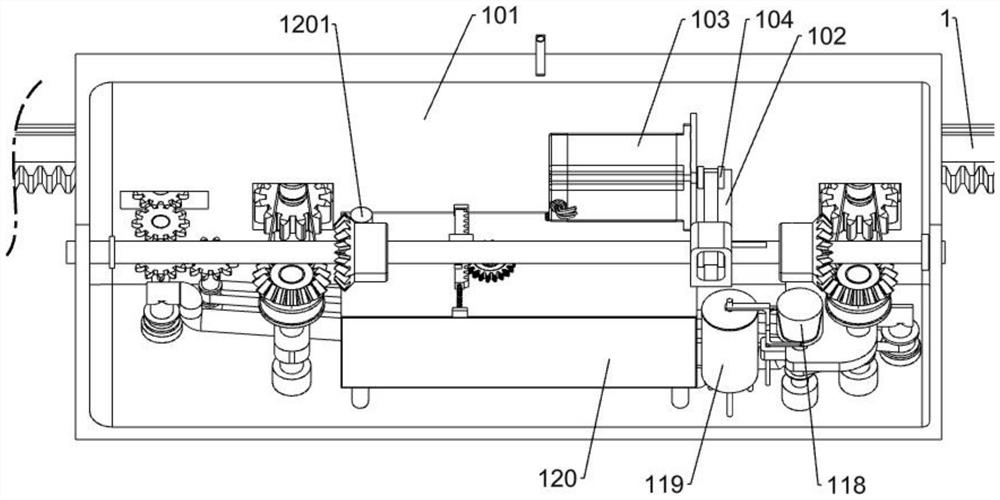
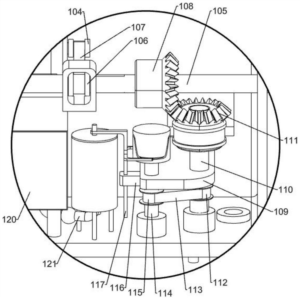
[0111] A hospital corridor positioning track hidden disinfection machine, such as Figure 1-6Shown, comprise rack chute 1, disinfection frame 101, motor support plate 102, power motor 103, first pulley 104, main rotating shaft 105, second pulley 106, first belt 107, first bevel gear 108, gear support plate 109, first shaft 110, third pulley 1101, fourth pulley 1102, first gear 1103, second belt 1104, second bevel gear 111, fifth pulley 112, third belt 113 , the second rotating shaft 114, the sixth pulley 115, the water pump connecting block 116, the pumping rod 117, the chute cylinder 118, the pressure water pump 119, the disinfection water tank 120, the water tank cover 1201, the first connecting pipe 121, the second connecting pipe 122, Two-way connecting pipe 123 and disinfection spray pipe 124, rack chute 1 is fixed on the body of wall, the rear side of disinfection frame 101 slides on rack chute 1, and the vertical section of disinfection frame 101 has three different rec...
Embodiment 2
[0114] Based on Example 1, such as Figure 7-8 As shown, the stirring mechanism includes a stirring gear 2, a rack limit frame 201, a short rack 202, a triangular block 203, a rotating contact rod 2031, a rack fixed block 204, a stirring spring 205, a stirring fan 206 and a stirring support rod 207, The stirring fan 206 passes through the top surface of the disinfection water tank 120, and the stirring fan 206 is rotationally connected with the disinfection water tank 120. The fan teeth of the stirring fan 206 are in the disinfection water tank 120, and the stirring gear 2 is fixedly connected to the upper end of the stirring fan 206. Above the water tank 120, there are two rack fixing blocks 204. The rack fixing blocks 204 are located on the top of the disinfection water tank 120 and placed symmetrically front and back. A cylindrical rod is fixed between the two rack fixing blocks 204, and the short rack 202 is slidingly connected. On the cylindrical rod between the two rack ...
Embodiment 3
[0117] Based on Example 1, such as Figure 9-11 As shown, the opening and closing mechanism includes a switch rack 3, a second gear 301, a third gear 302, a third rotating shaft 303, a short support plate 3031, a seventh pulley 304, a first switch 305, an eighth pulley 306, The fourth belt 307, the fourth gear 308, the fifth gear 309, the fourth rotating shaft 310, the ninth pulley 311, the fifth belt 312, the second switch 313 and the tenth pulley 314, the switch rack 3 is fixed on the tooth On the bar chute 1, the second gear 301 is fixed on the rotating shaft in the leftmost rectangular through hole of the disinfection frame 101, the second gear 301 can mesh with the switch rack 3, and the short support plate 3031 is fixed on the disinfection frame 101 on the left side of the vertical section, the third rotating shaft 303 is rotatably connected to the leftmost axle sleeve of the disinfection frame 101, the third rotating shaft 303 passes through the short support plate 3031...
PUM
 Abstract
Description
Claims
Application Information