
Seawater filter before a centrifugal backwash pump

A backwash pump and centrifugal technology, applied in the field of filters, can solve the problems of clogging, inconvenient use of the filter, affecting the use of the filter, etc., and achieve the effect of convenient use.

Active Publication Date: 2021-10-08
SHANDONG TRANSPORT VOCATIONAL COLLEGE
View PDF6 Cites 0 Cited by
  • Summary
  • Abstract
  • Description
  • Claims
  • Application Information

AI Technical Summary

Problems solved by technology

[0004] The purpose of the present invention is to solve the shortcomings of existing filters that are inconvenient to use, cannot handle the filter residue well, easily cause re-blocking, and affect the use of the filter, and propose a seawater filter in front of the centrifugal backwash pump

Method used


Image

  • Seawater filter before a centrifugal backwash pump
  • Seawater filter before a centrifugal backwash pump
  • Seawater filter before a centrifugal backwash pump

Examples


Embodiment 1

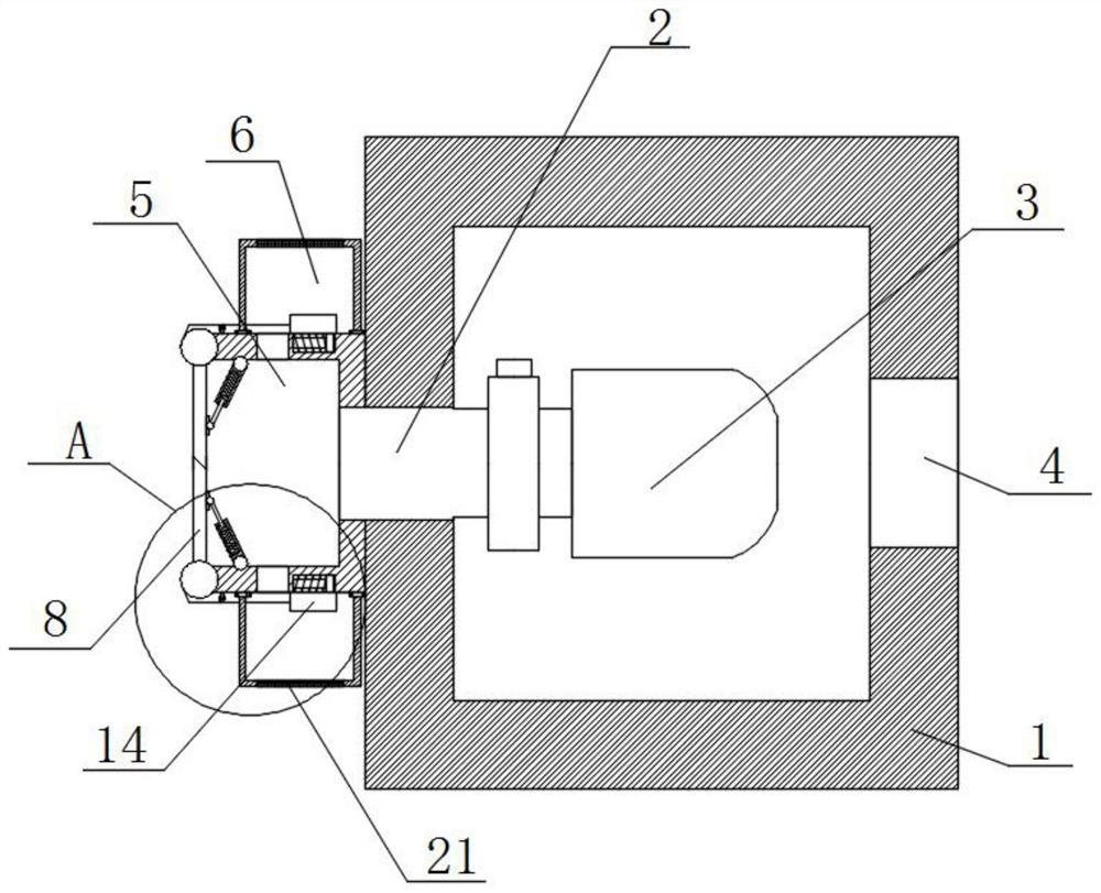
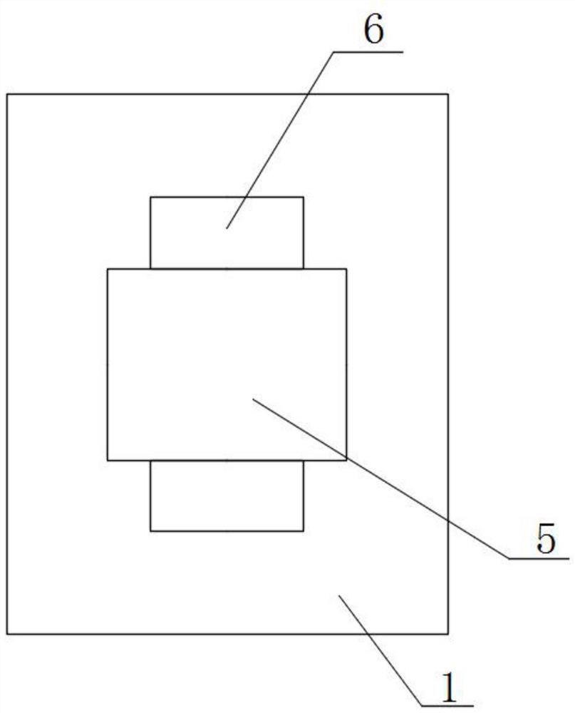
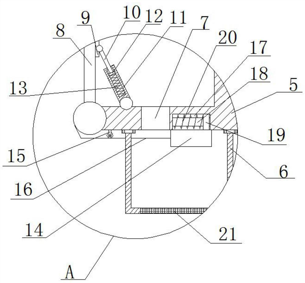
[0021] refer to Figure 1-3 , a seawater filter in front of a centrifugal backwash pump, comprising a box body 1, a water inlet 2 on one side of the box body 1, a first water outlet 4 is provided on one side of the box body 1, and a backwashing device is fixedly installed in the box body 1 Pump 3, a water inlet tank 5 is fixedly installed on one side of the box body 1, two filter residue boxes 6 are symmetrically fixedly installed on the water inlet tank 5, two second water outlets 7 are symmetrically opened on the water inlet tank 5, and the water inlet One side of case 5 is equipped with two case covers 8 symmetrically, and both case covers 8 are compatible with the water inlet box 5, and two baffle plates 14 are installed symmetrically on the water inlet box 5, and the two baffle plates 14 Respectively matched with the two second water outlets 7, two pulleys 15 are installed symmetrically on the water inlet tank 5, and a traction rope 16 is movable on the two pulleys 15, an...

Embodiment 2

[0027] refer to Figure 1-3 , a seawater filter in front of a centrifugal backwash pump, including a box body 1, a water inlet 2 on one side of the box body 1, a first water outlet 4 is provided on one side of the box body 1, and a screw is fixed in the box body 1. A backwash pump 3, one side of the box body 1 is fixed with a water inlet tank 5 by screws, two filter residue boxes 6 are symmetrically fixed on the water inlet tank 5 by screws, and two second filter boxes 6 are symmetrically installed on the water inlet tank 5. The water outlet 7 and one side of the water inlet tank 5 are symmetrically equipped with two case covers 8, both of which are compatible with the water inlet tank 5, and two baffle plates 14 are installed symmetrically on the water inlet tank 5. , two baffle plates 14 are matched with two second water outlets 7 respectively, two pulleys 15 are installed symmetrically on the water inlet tank 5, and traction ropes 16 are all movable on the two pulleys 15, a...


PUM


Abstract

The present invention belongs to the technical field of filters, in particular to a seawater filter in front of a centrifugal backwash pump. Aiming at the problem that the existing filter is inconvenient to use and cannot handle the filter residue well, it is easy to cause re-blocking and affect the use of the filter. The following scheme is proposed now, which includes a box body, a water inlet on one side of the box body, a first water outlet opening on one side of the box body, a backwash pump is fixedly installed in the box body, and an inlet is fixedly installed on one side of the box body. For the water tank, two filter residue boxes are symmetrically and fixedly installed on the water inlet tank, and two second water outlets are symmetrically opened on the water inlet tank, and two box covers are installed symmetrically on one side of the water inlet tank, and the two box covers are Matching with the water inlet box, two baffle plates are installed symmetrically slidingly on the water inlet box, and the two baffle plates are respectively adapted to the two second water outlets. The invention is convenient to use, can recycle the filter residue, prevents the filter from being blocked again, and affects the use of the filter.

Description

technical field [0001] The invention relates to the technical field of filters, in particular to a seawater filter before a centrifugal backwash pump. Background technique [0002] At present, the seawater filter before the pump installed on the ship generally adopts the standard CB / T497 or CBM1061. The filter is installed at the suction end of the seawater pump to intercept the larger particles of impurities in the seawater. However, at the input end of the seawater pump, the space where the filter is installed is very narrow, the filter is surrounded by pipelines or valves, the maintenance space is small, some filters are often submerged by stagnant water, and the front of the pump itself does not have a backwash function. The cleaning of the filter can only be done manually, which brings great inconvenience to the repair and maintenance of the filter, so a fully automatic backwash filter is needed. [0003] However, after the filter residue on the filter screen is washed...

Claims


Application Information

Patent Timeline
Patent Type & Authority Patents(China)
IPC IPC(8): B01D29/03B01D29/52B01D29/66
CPCB01D29/03B01D29/52B01D29/66
Inventor 王虎镇温磊朱英英曹兴飞张国凡
Owner SHANDONG TRANSPORT VOCATIONAL COLLEGE
Learn More