
Fixed rail component assembly line of two-section hidden rail production assembly line

A fixed rail and assembly line technology, applied in the direction of assembly machines, auxiliary devices, other manufacturing equipment/tools, etc., can solve the problems of uneven product quality, poor quality, poor control of assembly quality and assembly time schedule, etc., to achieve improvement The effect of production yield

Pending Publication Date: 2021-01-15
佛山市本吉智能科技有限公司
View PDF0 Cites 2 Cited by
  • Summary
  • Abstract
  • Description
  • Claims
  • Application Information

AI Technical Summary

Problems solved by technology

Due to manual assembly, the quality of the assembled products is uneven, the time is long, the quality is poor, and it is difficult to control the assembly quality and assembly time schedule.
During the installation process of the existing fixed rail assembly, the spring frame assembly needs to be welded to the corresponding position of the fixed rail, and then the bead frame assembly is plugged and slid with the "L"-shaped flange of the fixed rail, and then the movable rail assembly is simultaneously connected to the The bead frame assembly and the flange of the fixed rail are plugged and slid, so as to realize the pre-installation of the fixed rail assembly, and then carry out gear punching on the corresponding position of the slide rail to reduce the separation of the movable rail assembly and the fixed rail, and the above steps are basically The process is relatively cumbersome to operate manually. With the increase of labor costs year by year, the quality of China's manufacturing industry continues to rise, and the company's business scope increases. There is an urgent need for a fully automatic assembly line that can automatically assemble fixed rail components.

Method used


Image

  • Fixed rail component assembly line of two-section hidden rail production assembly line
  • Fixed rail component assembly line of two-section hidden rail production assembly line
  • Fixed rail component assembly line of two-section hidden rail production assembly line

Examples


Embodiment Construction

[0035] The present invention will be further described in detail below in conjunction with the accompanying drawings and specific embodiments. Terms such as "upper", "inner", "middle", "left", "right" and "one" quoted in this specification are only for the convenience of description, and are not used to limit the scope of the present invention. The scope of implementation and the change or adjustment of its relative relationship shall also be regarded as the scope of implementation of the present invention without substantive changes in technical content.

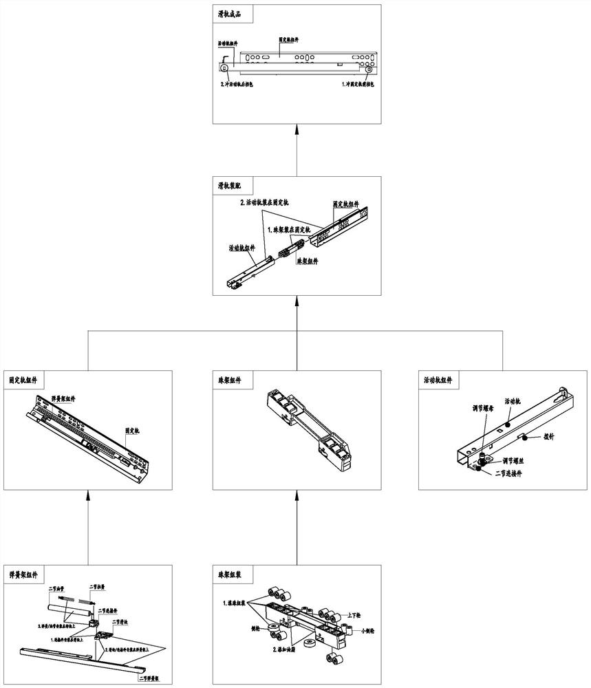
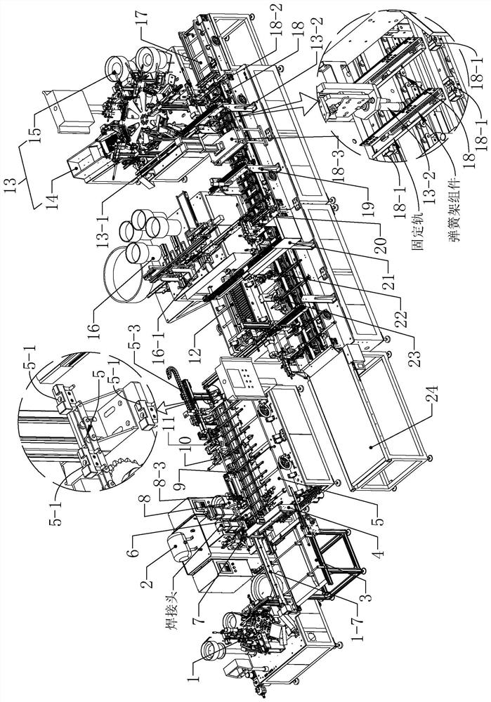
[0036] refer to Figure 1 to Figure 2 As shown, the two-section hidden rail includes a fixed rail provided with a spring frame assembly, a bead frame assembly, and a movable rail assembly, wherein the movable rail assembly includes a movable rail in the shape of a square tube, and one side of the movable rail is provided with a groove along its length. The opening extending in the direction of the opening, the movable rail...


PUM


Abstract

The invention discloses a fixed rail component assembly line of a two-section hidden rail production assembly line. In the production process, when a finished product assembly conveying belt conveys fixed rails one by one, a spring frame component clamping piece realizes the operation of matching a spring frame component with the fixed rails, and a spring frame welding machine is used for weldingthe spring frame component; a bead frame component is spliced and matched with flanges of the fixed rails by a bead frame component clamping piece, the movable rail component on a movable rail storagemachine is spliced and matched with the positions of the flanges of the fixed rails and the bead frame component by an assembly clamping mechanism, and the corresponding position of a slide rail structure is stamped and formed by a punching fixed rail gear mechanism; due to the pressing marks formed by stamping, a situation that the movable rail is separated from the fixed rail is reduced favorably, and finally the overall structure of the fixed rail assembly is formed. The production rhythm of the production line is coordinated through multiple devices, so that labor is saved, and the production efficiency and the product percent of pass can be improved.

Description

technical field [0001] The invention relates to the technical field of slide rail assembly equipment, in particular to a fixed rail component assembly line of a two-section concealed rail production assembly line. Background technique [0002] Slide rails, also known as guide rails and slideways, refer to hardware connection parts fixed on the cabinet body of furniture for the drawers or cabinet boards of furniture to enter and exit. Suitable for drawer connections in cabinets, furniture, etc. There is a two-section hidden rail, which includes a fixed rail, and the fixed rail is slidably connected with a movable rail. In order to realize the function of automatically sliding out the movable rail after the drawer is squeezed inward, and to improve the flexibility of the sliding movement of the movable rail , to reduce jamming. Therefore, a spring frame is set at the end of the movable rail facing the fixed rail, and a spring set is arranged in the spring frame. Using the res...

Claims


Application Information

Patent Timeline
IPC IPC(8): B23P21/00B23P23/06B23K31/02B23K37/04B23K37/00
CPCB23P21/004B23P19/001B23P23/06B23K31/02B23K37/0435B23K37/00
Inventor 梁大伟吴辉张堂梁霍敏耀邱新福陈游国曾伟宋玉玮
Owner 佛山市本吉智能科技有限公司
Learn More