Part polishing operation table with automatic scrap collecting function for machine manufacturing
An automatic collection and mechanical manufacturing technology, which is applied in the field of parts grinding, can solve the problems of a large amount of grinding dust and waste, the health hazards of environmental operators, and the tendency to cut hands, so as to reduce grinding dust, improve environmental protection, and improve cleanliness The effect of strength
- Summary
- Abstract
- Description
- Claims
- Application Information
AI Technical Summary
Problems solved by technology
Method used
Image
Examples
Embodiment 1
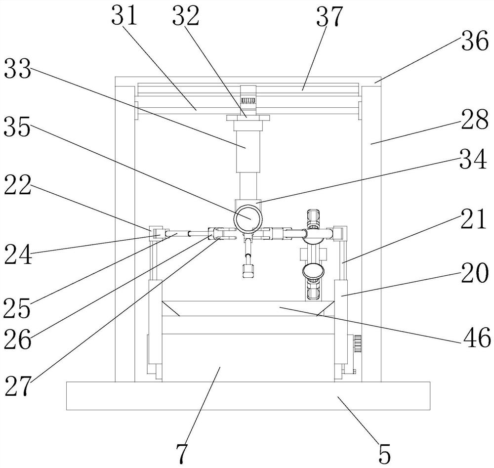
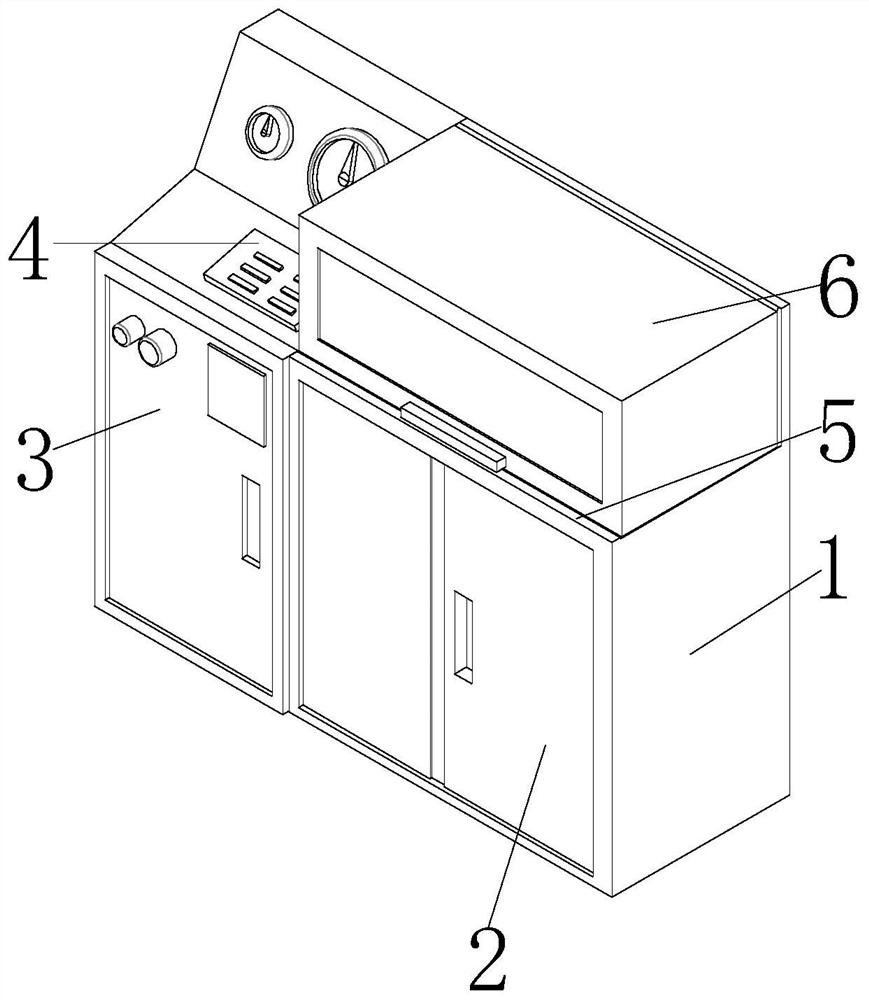
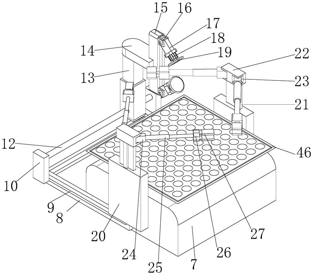
[0029] see Figure 1-7 , the present invention provides a technical solution: a mechanical manufacturing parts grinding operation table with the function of automatic collection of debris, including a device body 1, a base base 5 is fixedly installed on the top of the device body 1, and a base base 5 is fixedly installed on the top of the base base 5 There is a first box body 7, and both sides of the first box body 7 are fixedly equipped with a fixed plate 8, and the inside of the fixed plate 8 is provided with a first sliding groove 9, and the outside of the first sliding groove 9 is movable. A sliding block 10, one side of the first sliding block 10 is fixed with a fixed knob 11, the other side of the first sliding block 10 is fixed with a first rod 12, and the outside of the first rod 12 is fixed with a telescopic device 13. A first connection block 14 is fixedly installed on the top of the telescopic device 13, and a second connection block 15 is fixedly installed at the e...
Embodiment 2
[0032] see Figure 1-7, on the basis of Embodiment 1, the present invention provides a technical solution: the inside of the second connecting block 15 is provided with a chute, and the outside of the chute is movably installed with a second sliding block 16, and the inside of the second sliding block 16 A connecting groove is provided, and a rotating block 17 is movably installed inside the connecting groove, a driving motor 18 is fixedly installed at the end of the rotating block 17, and a first grinding device 19 is fixedly installed at the driving end of the driving motor 18.
[0033] In this embodiment, a chute is provided inside the second connecting block 15, and the second sliding block 16 is movably installed on the outside of the chute, so that the relevant side grinding device moves through the second sliding block 16, so that the overall The grinding operation is more precise, and the inside of the second sliding block 16 is provided with a connecting groove, and t...
Embodiment 3
[0035] Such as Figure 1-7 As shown, on the basis of Embodiment 1 and Embodiment 2, the present invention provides a technical solution: a suction fan 45 is fixedly installed on the top of the first box body 7, and a connecting cover frame 46 is fixedly installed on the outside of the suction fan 45, The inside of the equipment body 1 is fixedly equipped with a partition 43, the top of the partition 43 is fixedly equipped with a collection box 44, the bottom of the partition 43 is fixedly installed with a power supply, and the bottom of the first box body 7 is connected with a feeding pipe, and the feeding The tube extends through the device body 1 and the base base 5 to the interior of the collection box 44 .
[0036] In this embodiment, a suction fan 45 is fixedly installed on the top of the first box body 7, which is convenient for absorbing and processing related debris for grinding, so that the collection operation of related debris is more efficient. The cover frame 46 ...
PUM
 Abstract
Description
Claims
Application Information
 - R&D
- Intellectual Property
- Life Sciences
- Materials
- Tech Scout
- Unparalleled Data Quality
- Higher Quality Content
- 60% Fewer Hallucinations
Browse by: Latest US Patents, China's latest patents, Technical Efficacy Thesaurus, Application Domain, Technology Topic, Popular Technical Reports.
© 2025 PatSnap. All rights reserved.Legal|Privacy policy|Modern Slavery Act Transparency Statement|Sitemap|About US| Contact US: help@patsnap.com


