Eureka AIR delivers breakthrough ideas for toughest innovation challenges, trusted by R&D personnel around the world.

Winding speed regulating mechanism for polyethylene terephthalate (PET) aluminum foil production

A technology of speed regulating mechanism and aluminum foil, which is applied in the direction of winding strips, function indication, thin material processing, etc., can solve the problems of large pulling force of aluminum foil, damage of aluminum foil, etc., and achieve the effect of reducing the rotation speed

Inactive Publication Date: 2021-01-15
广东芭沐思日化有限公司
View PDF0 Cites 2 Cited by
  • Summary
  • Abstract
  • Description
  • Claims
  • Application Information

AI Technical Summary

Problems solved by technology

[0005] Aiming at the deficiencies of the prior art, the present invention provides a winding speed regulating mechanism for PET aluminum foil production, which has the advantages of automatically adjusting the speed of the winding roller as the winding progresses, and preventing the PET aluminum foil from being subjected to increasing tension. , to solve the problem that during the rewinding process of a general rewinding device, with the increase of PET aluminum foil on the rewinding roller, the rewinding speed of the PET aluminum foil is getting faster and faster, which leads to a greater and greater pulling force on the aluminum foil, which is easy to cause The problem of damaged aluminum foil

Method used


Image

  • Winding speed regulating mechanism for polyethylene terephthalate (PET) aluminum foil production
  • Winding speed regulating mechanism for polyethylene terephthalate (PET) aluminum foil production
  • Winding speed regulating mechanism for polyethylene terephthalate (PET) aluminum foil production

Examples


Embodiment Construction

[0024] The following will clearly and completely describe the technical solutions in the embodiments of the present invention with reference to the accompanying drawings in the embodiments of the present invention. Obviously, the described embodiments are only some, not all, embodiments of the present invention. Based on the embodiments of the present invention, all other embodiments obtained by persons of ordinary skill in the art without making creative efforts belong to the protection scope of the present invention.

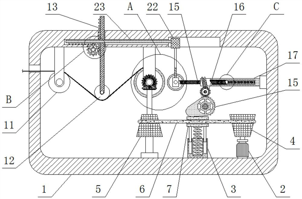
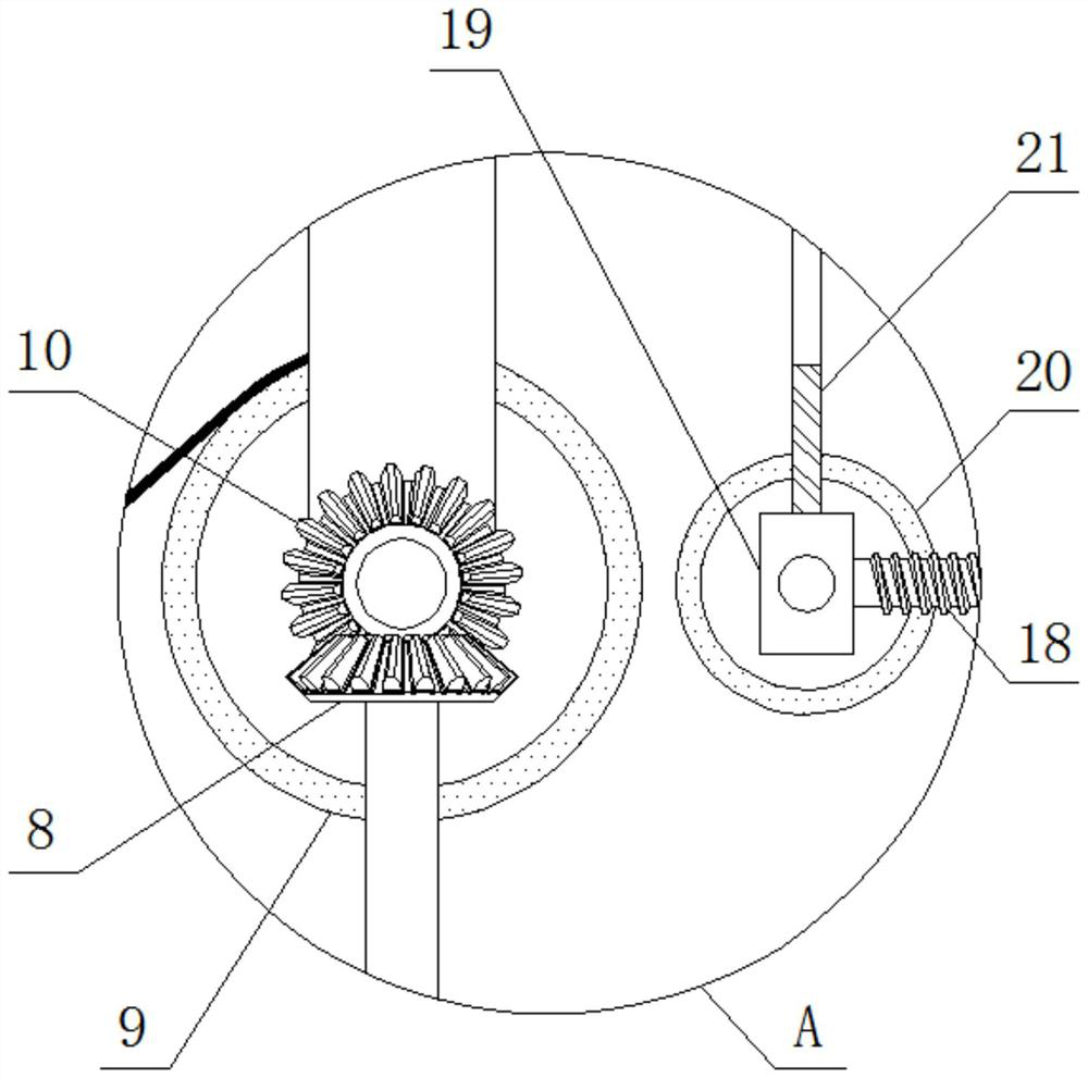
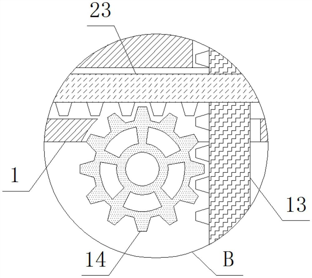
[0025] see Figure 1-5 , a winding speed regulating mechanism for PET aluminum foil production, comprising a box body 1, the inner bottom wall of the box body 1 is fixedly connected with a motor 2 and a fixed frame 3, the top of the motor 2 is connected with a first conical wheel 4 for rotation, the box body The inner bottom wall of the body 1 is rotatably connected with a second cone wheel 5, a belt 6 is sleeved between the first cone wheel 4 and the second c...


PUM


Abstract

The invention relates to the technical field of aluminum foil winding, and discloses a winding speed regulating mechanism for polyethylene terephthalate (PET) aluminum foil production. The winding speed regulating mechanism for PET aluminum foil production comprises a box body, wherein a movable rod is inserted into the top of the box body; a movable roller is rotatably connected to the bottom ofthe movable rod; a first gear is rotatably connected to the inner bottom wall of the box body; two rotating cylinders are rotatably connected to the inner right wall of the box body; threaded rods areinserted into the left sides of the two rotating cylinders correspondingly; fixing blocks are fixedly connected to the left sides of the two threaded rods correspondingly; a triangular frame is fixedly connected to the tops of the two fixing blocks; a sliding block is fixedly connected to the top of the triangular frame; and a transverse rod is fixedly connected to the left side of the sliding block. When the fixing blocks move rightwards, the movable roller is driven to press an aluminum foil downwards through cooperation of the triangular frame, the sliding block, the transverse rod, the first gear and the movable rod, so that the aluminum foil is in a tensioned state, and the situation that after the rotating speed of the winding roller is reduced, the aluminum foil behind passes through the rotating roller at the original speed under the inertia effect, and consequently the tension of the aluminum foil is too small before winding so as to generate gaps is prevented.

Description

technical field [0001] The invention relates to the technical field of aluminum foil winding, in particular to a winding speed regulating mechanism for PET aluminum foil production. Background technique [0002] Aluminum foil is a hot stamping material that is directly rolled into thin sheets of metal aluminum. Its hot stamping effect is similar to that of pure silver foil hot stamping, so it is also called fake silver foil. Aluminum foil is widely used in food and beverages because of its excellent characteristics. , cigarettes, medicines, photographic bottom plates, household daily necessities, etc., usually used as packaging materials; electrolytic capacitor materials; heat insulation materials for buildings, vehicles, ships, houses, etc.; can also be used as decorative gold and silver threads, wallpapers, and various stationery prints and Decoration trademarks of light industrial products, etc. [0003] After the PET aluminum foil is produced, the aluminum foil needs to...

Claims


Application Information

Patent Timeline
Patent Type & Authority Applications(China)
IPC IPC(8): B65H18/10B65H18/26B65H23/198B65H23/16
CPCB65H18/10B65H18/26B65H23/16B65H23/198B65H2511/14B65H2513/10B65H2701/1732B65H2220/01B65H2220/02
Inventor 林燕旋
Owner 广东芭沐思日化有限公司
Why Eureka
Eureka Blog
Learn More