Soap stamping device

A stamping and soaping technology, applied in embossing/polishing soap, etc., can solve the problems of different stamping depths on the soap surface, low operating efficiency, and easy fatigue

Active Publication Date: 2021-01-15
HUIZHOU MUSCLE MARGIN BIOLOGICAL POLYTRON TECH INC
View PDF6 Cites 0 Cited by
  • Summary
  • Abstract
  • Description
  • Claims
  • Application Information

AI Technical Summary

Problems solved by technology

[0005] In order to overcome the need for the staff to cut the large soap board formed by the condensation of the soap base into soap bases, stamp the upper surface of a piece of soap with a hand-held printing plate, and then pick up the next piece of soap to repeat the operation, this long-term operation is inefficient and prone to fatigue. The shortcomings of different depths of stamping on the surface of soap, the technical problem of the present invention: provide a soap stamping device with simple structure, convenient operation, and basically the same depth of stamping on the surface of soap

Method used


Image

  • Soap stamping device
  • Soap stamping device
  • Soap stamping device

Examples


Embodiment 1

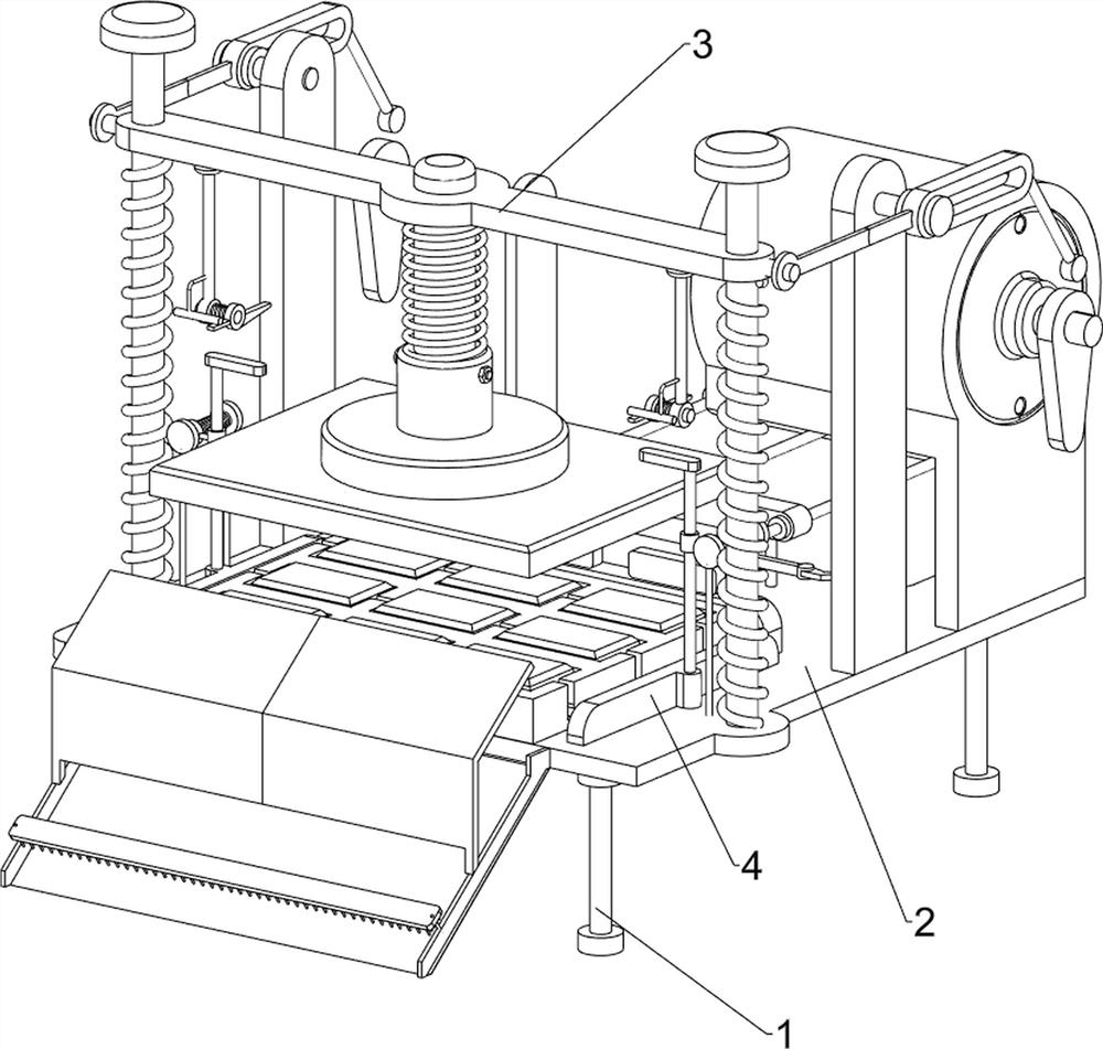
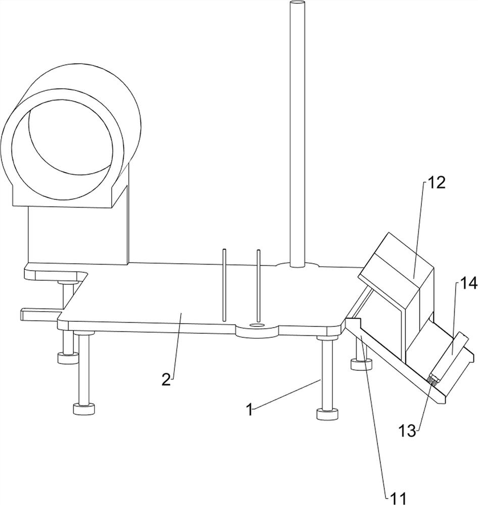
[0022] like figure 1 , figure 2 and image 3 As shown, a soap stamping device includes a support column 1, a worktable 2, a stamping mechanism 3 and a stripping mechanism 4, the four corners of the bottom of the workbench 2 are provided with support columns 1, and the top of the workbench 2 is provided with There is a stamping mechanism 3, and a stripping mechanism 4 is arranged on the top of the workbench 2, and the stripping mechanism 4 is located below the stamping mechanism 3.

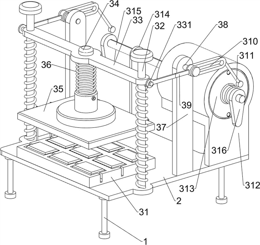
[0023] Stamping mechanism 3 comprises placement table 31, column 32, first connecting rod 33, first elastic member 331, round rod 34, printing plate 35, second elastic member 36, first bearing seat 37, fixed shaft 38, the first Two connecting rods 39, chute 310, fork 311, fixed seat 312, biaxial motor 313, second bearing seat 314, first rotating shaft 315 and cam 316, the front side of the top of the workbench 2 is provided with a placement platform 31, the placement platform 31 is evenly space...

Embodiment 2

[0027] like Figure 4 and Figure 5 As shown, on the basis of Embodiment 1, a soap imprinting device also includes a second fixed block 5, a slide bar 6, a push plate 7, a connecting plate 8, a driving lever 9 and an elastic pawl 10, and a working table 2. A second fixed block 5 is arranged on the rear side of the top, and sliding rods 6 are evenly spaced inside the second fixed block 5. Push plates 7 are arranged at the front ends of the sliding rods 6, and connecting plates are arranged between the rear ends of the sliding rods 6. 8. The front sides of the slide bars 6 on the left and right sides are symmetrically provided with driving rods 9 , and the outer sides of the two driving rods 9 are provided with elastic pawls 10 , and the elastic pawls 10 cooperate with the second guide rods 45 which are similar.

[0028] The top plate 49 moves upwards and ejects the stamped soap from the three square holes of the placing table 31. The staff closes the biaxial motor 313, holds t...


PUM


Abstract

The invention relates to a stamping device, in particular to a soap stamping device. The soap stamping device is simple in structure, convenient to operate and basically consistent in depth of soap surface stamping. The soap stamping device provided by the invention comprises supporting columns, wherein the supporting columns are arranged at the four corners of the bottom of a workbench; a stamping mechanism which is arranged at the top of the workbench; and a stripping mechanism which is arranged at the top of the workbench, wherein the stripping mechanism is located below the stamping mechanism. When the cam rotates clockwise and extrudes the swing rod, the first connecting rod drives the printing plate to continue to move downwards through the round rod to stamp soap on the upper surface, and the second elastic piece and the round rod can play a role in guiding and buffering the printing plate.

Description

technical field [0001] The invention relates to a stamping device, in particular to a soap stamping device. Background technique [0002] Trademarks are used to distinguish the source of goods or services. They are signs with distinctive features and are the product of modern economy. In the commercial arena, trademarks protect trademark holders by ensuring that they have the exclusive right to use them to identify goods or services, or to license others to use them for compensation. [0003] Soap is a cleaning and emulsifying agent. In the classification of trademarks, soap belongs to cosmetic daily chemicals. Basic raw materials such as animal oil, vegetable oil and rosin are degummed, alkali refined, saponified, salted out, washed, alkali washed, and sorted. After the soap base is formed, on the production line, the staff needs to cut the large soap board formed by the condensation of the soap base into a soap base, stamp the upper surface of a piece of soap with a hand-...

Claims


Application Information

Patent Timeline
IPC IPC(8): C11D13/28
CPCC11D13/28
Inventor 方转娣
Owner HUIZHOU MUSCLE MARGIN BIOLOGICAL POLYTRON TECH INC
Why Eureka
Try Eureka