Exhaust gas turbocharger pressure shell with bypass flow path
A technology of exhaust gas turbine and bypass flow, applied in machine/engine, engine components, mechanical equipment, etc., can solve the problems of airflow obstruction assembly accuracy, poor efficiency, etc., to improve assembly accuracy and work efficiency, improve fluency, reduce howling effect
- Summary
- Abstract
- Description
- Claims
- Application Information
AI Technical Summary
Problems solved by technology
Method used
Image
Examples
Embodiment Construction
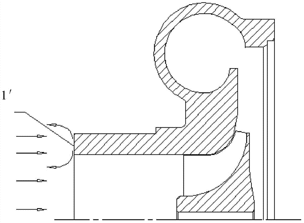
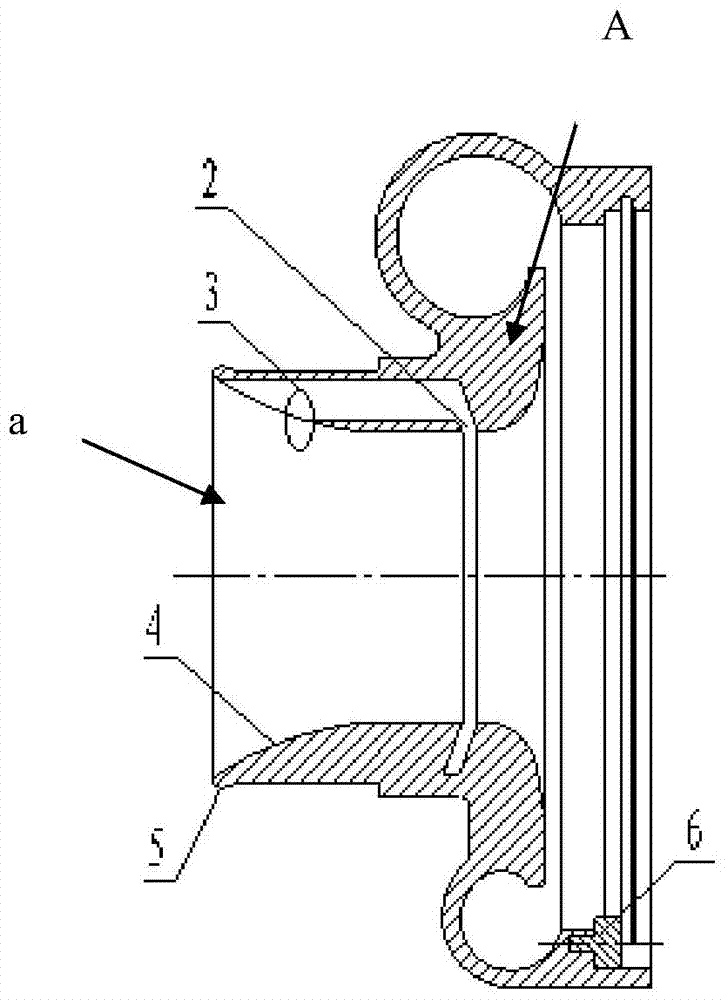
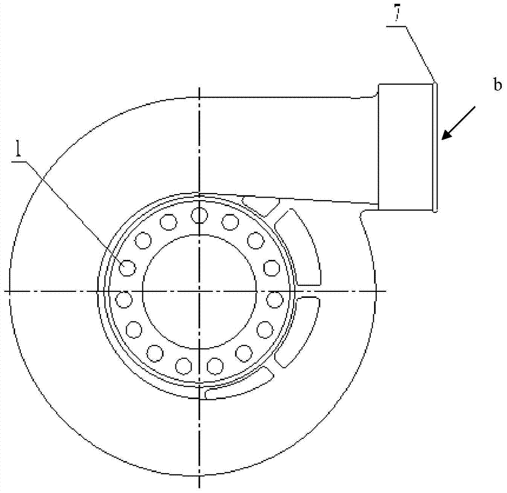
[0022] Such as figure 2 , image 3 , Figure 4 As shown, the pressure casing of the exhaust gas turbocharger with a bypass flow channel includes an air inlet a and an air outlet b arranged on the body A of the pressure casing, and several suction ports are arranged in the inner edge of the air inlet a Hole 1, the hole wall at the inner end of the inner hole of the air inlet a is provided with an air supply groove 2, the inner wall surface of the outer end of the inner hole of the air inlet a is set as an arc surface 4, and one end of the suction hole 1 passes through the arc surface The air return port 3 is formed, and the other end is connected to the air supply groove 2. The air suction hole 1, the air return port 3 and the air supply groove 2 form a bypass flow channel. These air suction holes 1 are arranged on the arc surface 4 of the inner edge of the pressure shell air inlet Holes forming a relatively axial circular array, such as Figure 5 As shown, the right end of...
PUM
 Abstract
Description
Claims
Application Information
 - R&D
- Intellectual Property
- Life Sciences
- Materials
- Tech Scout
- Unparalleled Data Quality
- Higher Quality Content
- 60% Fewer Hallucinations
Browse by: Latest US Patents, China's latest patents, Technical Efficacy Thesaurus, Application Domain, Technology Topic, Popular Technical Reports.
© 2025 PatSnap. All rights reserved.Legal|Privacy policy|Modern Slavery Act Transparency Statement|Sitemap|About US| Contact US: help@patsnap.com


