Flow adjusting structure

A technology of blades and air inlets, which is applied in the direction of mufflers, engine components, machines/engines, etc., which can solve the problems of accelerated carrier aging, air intake flanges that cannot adjust the airflow velocity, and large airflow velocity, so as to achieve uniform velocity and facilitate The effect of promoting the use and prolonging the service life

Inactive Publication Date: 2016-06-01
WUHU EVERSHINE AUTOMOTIVE COMPONENT
View PDF5 Cites 0 Cited by
  • Summary
  • Abstract
  • Description
  • Claims
  • Application Information

AI Technical Summary

Problems solved by technology

[0006] The purpose of the present invention is to overcome the problem that the air intake flange in the automobile exhaust system cannot adjust the airflow velocity in the prior art, so that the airflow velocity is relatively high, and the aging of the carrier is accelerated, and a rectification structure is provided, which can rectify and adjust the airflow , prolong carrier life

Method used


Image

  • Flow adjusting structure
  • Flow adjusting structure

Examples


Embodiment 1

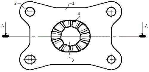
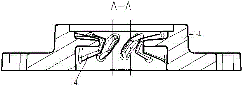
[0024] Combine figure 1 with figure 2 As shown, a rectifying structure of this embodiment includes an air inlet flange formed by one-time casting. The air inlet flange includes a flange body 1 and a blade 4. The flange body 1 is provided with mounting holes 2 around the flange. An air inlet 3 is provided in the middle of the main body 1, and fan-shaped blades 4 are evenly distributed in the inner circumferential direction of the air inlet 3, which can better guide and buffer the airflow. Each blade 4 is tapered in size along the direction extending from the inner side of the air inlet 3 to the center of the air inlet 3 (that is, the length of the corresponding arc segment at the center of each blade 4 close to the air inlet 3 gradually decreases. Small), each blade 4 is distributed obliquely on the inner side of the inlet 3, and the inclination direction is the same. Each blade 4 is distributed clockwise or counterclockwise on the inner circumference of the inlet 3 (that is, t...

Embodiment 2

[0027] The basic structure of a rectifying structure of this embodiment is the same as that of Embodiment 1, and the difference is that the included angle δ in this embodiment is 30°.


PUM


Abstract

The invention discloses a flow adjusting structure, and belongs to the field of vehicle exhaust systems. The flow adjusting structure comprises an air inlet flange, wherein the air inlet flange comprises a flange body and a plurality of blades; mounting holes are formed in the periphery of the flange body; an air inlet is formed in the middle of the flange body; the blades are fan-shaped, and uniformly distributed at the circumference on the inner side of the air inlet; the size of each blade in the extending direction from the inner side of the air inlet to the center of the air inlet becomes smaller and smaller; and the included angle Delta between each blade and the axis of the air inlet is 30 to 45 degrees. During use, the fan-shaped blades distributed on the inner side of the air inlet can perform a flow adjusting effect on air flow, so that the adjusted air flow is relatively uniform in speed when reaching the surface of a carrier, the utilization ratio of the carrier is enhanced, the maximum speed peak value on the surface of the carrier is lowered, the effect of protecting the carrier and a gasket from blowing is performed, and the service lives of the vehicle exhaust systems can be prolonged.

Description

technical field [0001] The invention relates to the technical field of automobile exhaust, more specifically, relates to a rectification structure used in the catalytic converter part of the automobile exhaust system. Background technique [0002] An automobile exhaust system refers to a system that collects and emits exhaust gas, and generally consists of an exhaust manifold, an exhaust pipe, a catalytic converter, an exhaust temperature sensor, an automobile muffler, and an exhaust tailpipe. The automobile exhaust system mainly discharges the exhaust gas from the engine, and at the same time reduces the pollution of the exhaust gas and reduces the noise. Automobile exhaust systems are mainly used in light vehicles, mini-cars, passenger cars, motorcycles and other motor vehicles. [0003] In the automobile exhaust system, the connection between each assembly or each component is mostly connected by flanges, in which the exhaust manifold assembly and the catalytic converter...

Claims


Application Information

Patent Timeline
IPC IPC(8): F01N3/28F01N13/18
CPCF01N3/2892F01N13/1844Y02A50/20
Inventor 刘华杨涛
Owner WUHU EVERSHINE AUTOMOTIVE COMPONENT
Why Eureka
Try Eureka