Jeans distressing and polishing device
A technology of jeans and edging mechanism, applied in textile and papermaking, fabric surface trimming, thorn pattern, etc., can solve the problems of low efficiency, waste of operator manpower, etc., to improve production efficiency, save workload, and ensure stability. Effect
- Summary
- Abstract
- Description
- Claims
- Application Information
AI Technical Summary
Problems solved by technology
Method used
Image
Examples
Embodiment 1
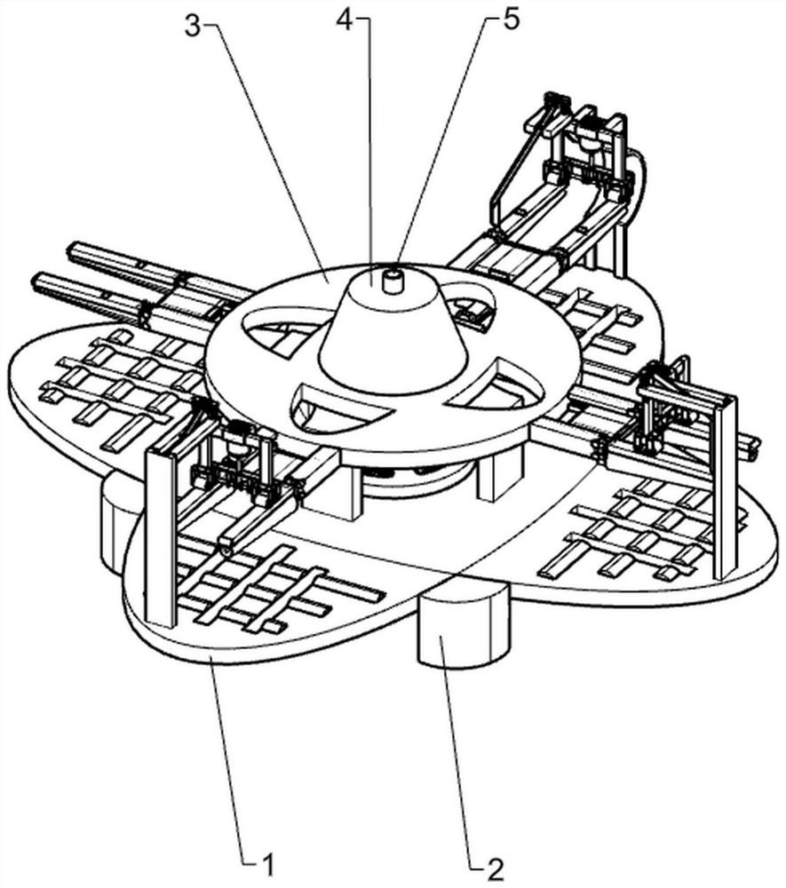
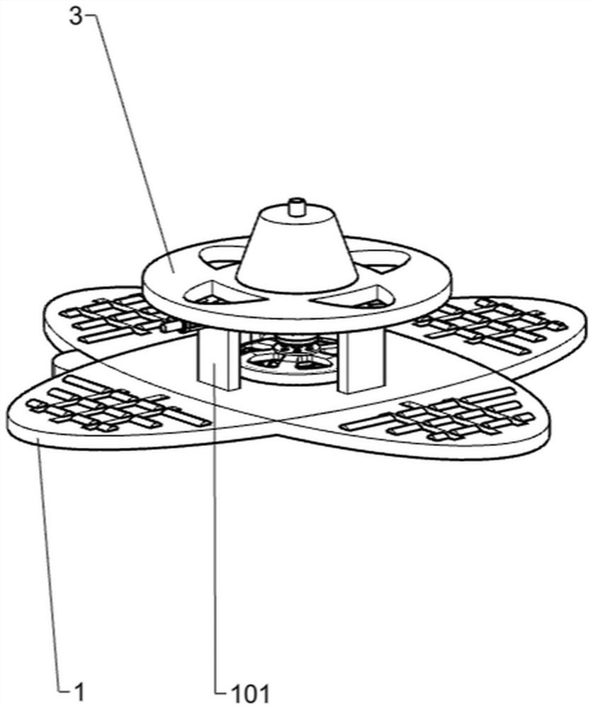
[0094] Such as Figure 1-Figure 14 As shown, a kind of old-fashioned polishing device for jeans includes a support table 1, a first support plate 101, a fixed table 2, a turntable 3, a turntable 4, a first rotating rod 5, a power mechanism, a support mechanism and an edge grinding mechanism. Two support platforms 1 are symmetrically folded together to form a whole, two first support plates 101 are fixedly installed on the front right sides of the support platform 1, four fixed platforms 2 are fixedly installed on the four crossing edges of the support platform 1, and the turntable 3 is located above the first supporting plate 101, the turntable 4 is fixedly installed in the middle position above the turntable 3, one end of the first rotating rod 5 is fixedly connected with the middle position of the turntable 3 and the turntable 4, and the power mechanism is fixedly installed in the middle of the support platform 1 Position, the power mechanism is fixedly connected with the fi...
Embodiment 2
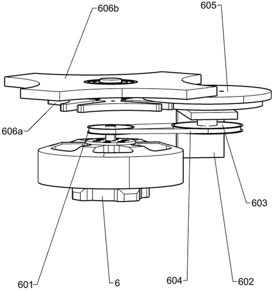
[0097] Such as image 3 As shown, on the basis of Embodiment 1, the power mechanism includes a first motor 6, a first pulley 601, a second support plate 602, a second pulley 603, a belt 604, a dial 605, an intermittent disc 606a and The support plate 606b, the first motor 6 is fixedly installed at the middle position of the support platform 1, the first pulley 601 is fixedly installed at the upper end of the output shaft of the first motor 6, and the second support plate 602 is fixedly installed at the middle position of the support platform 1 , the second support plate 602 is located at the left rear side of the first motor 6, the second pulley 603 is rotatably mounted on the lower middle part of the horizontally placed plate of the second support plate 602, and the belt 604 is wound around the first pulley 601 and the second pulley 601. On the second pulley 603, the dial 605 is rotatably installed on the upper side of the second support plate 602, the intermittent disc 606a ...
Embodiment 3
[0106] Such as Figure 13-Figure 14 As shown, according to Embodiment 1 or Embodiment 2, it also includes a third bracket 12, a fourth bracket 1201, a second pole 11, a second connecting column 1101, a third pole 1102, a fourth fixing plate 1103, a fourth Two rotating rods 1104, the second rotating drum 1105 and the second scrubbing belt 1106, the third support 12 is fixedly installed on the rear side of the support platform 1, the fourth support 1201 is fixedly installed on the left side of the third support 12, and the two second The pole 11 is fixedly installed on the front upper end of the fourth bracket 1201, the second connecting column 1101 is fixedly installed on the front end of the second pole 11, the third pole 1102 is connected with the second connecting column 1101 in rotation, and the fourth fixing plate 1103 is fixed Installed on the lower end of the third pole 1102, the fourth fixed plate 1103 is slidably connected with the upper end of the slider 7063, the two...
PUM
 Abstract
Description
Claims
Application Information
 - R&D
- Intellectual Property
- Life Sciences
- Materials
- Tech Scout
- Unparalleled Data Quality
- Higher Quality Content
- 60% Fewer Hallucinations
Browse by: Latest US Patents, China's latest patents, Technical Efficacy Thesaurus, Application Domain, Technology Topic, Popular Technical Reports.
© 2025 PatSnap. All rights reserved.Legal|Privacy policy|Modern Slavery Act Transparency Statement|Sitemap|About US| Contact US: help@patsnap.com


