
Iris diaphragm type reducing valve

A technology of valves and apertures, applied in the direction of sliding valves, valve details, valve devices, etc., can solve the problems of single function and limited application range, and achieve the effect of wide application range and changing the interception area

Pending Publication Date: 2021-01-15
WUHAN YANLING INTELLIGENT TECH CO LTD
View PDF0 Cites 7 Cited by
  • Summary
  • Abstract
  • Description
  • Claims
  • Application Information

AI Technical Summary

Problems solved by technology

However, the valves listed above play a relatively single role in pipeline flow, resulting in a very limited range of application.

Method used


Image

  • Iris diaphragm type reducing valve
  • Iris diaphragm type reducing valve
  • Iris diaphragm type reducing valve

Examples


Embodiment Construction

[0026] The present invention will be further described below in conjunction with accompanying drawing.

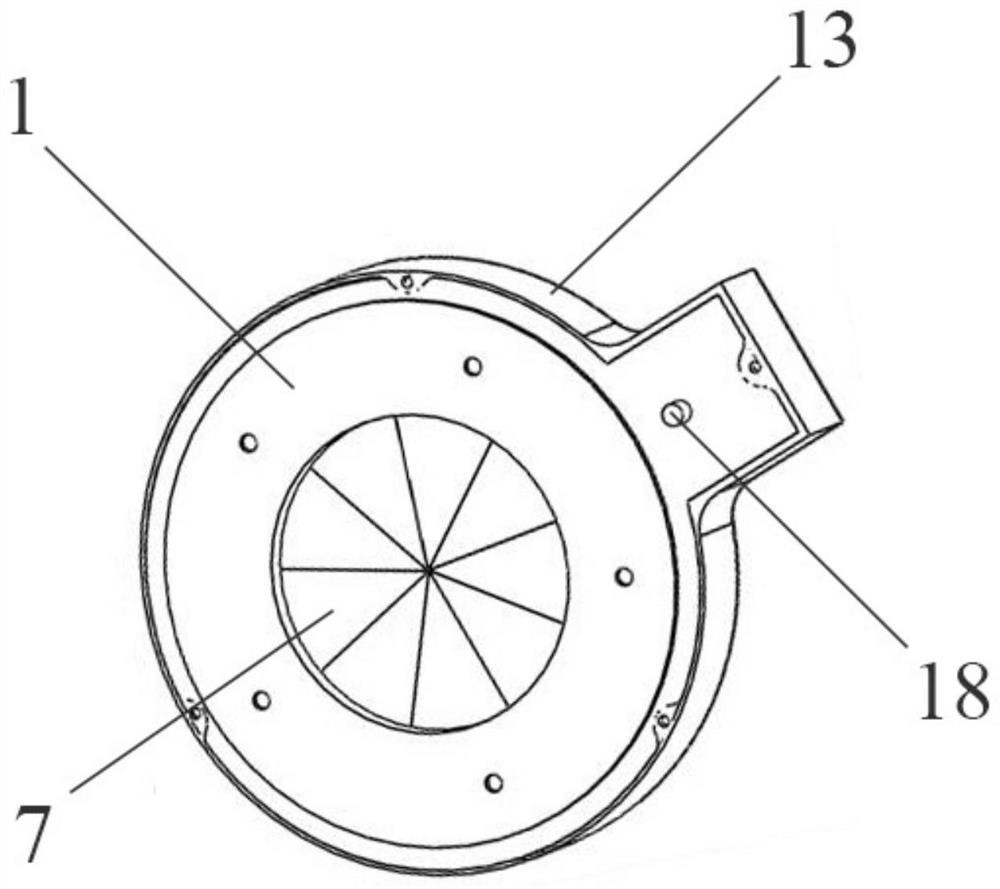
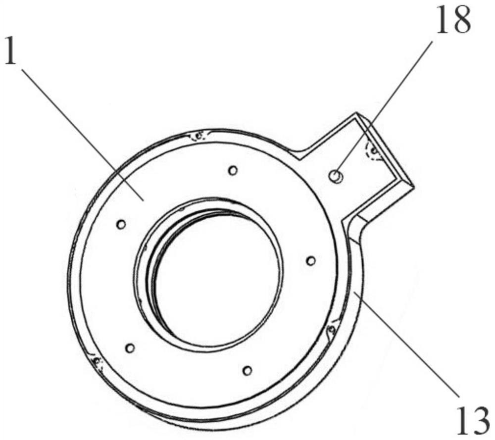
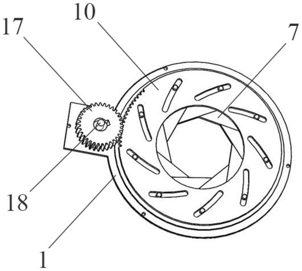
[0027] see Figure 1-3 As shown, an iris diaphragm variable diameter valve includes a valve housing, a control panel 10 disposed in the inner cavity of the valve housing, N fan blades 7 and a drive gear 17, and the number of blades 7 in the figure is nine.

[0028] see Figure 4-7 As shown, the valve housing includes a chassis 1 and an end cover 13 that have the same outer contour and are aligned and snap-fitted. The main body of the chassis 1 is annular and its outer circumference is provided with a first protrusion 2 integrally formed with it. The inner surface of the main body of the chassis 1 is uniformly provided with N non-penetrating linear grooves 6 along its circumference, as shown in the figure The number of linear grooves 6 is 9, and the connecting hole 5 is provided on the first protrusion 2 ; the main body of the end cap 13 is annular, and the second protrusi...


PUM


Abstract

The invention discloses an iris diaphragm type reducing valve. The iris diaphragm type reducing valve comprises a valve shell, a control panel, N blades and a driving gear, wherein the control panel,the N blades and the driving gear are arranged in an inner cavity of the valve shell. The valve shell comprises a base plate and an end cover. A base plate body is annular, and a first protrusion integrally formed with the base plate body is arranged on the outer circumference of the base plate body. An end cover body is annular, and a second protrusion integrally formed with the end cover body isarranged on the outer circumference of the end cover body. The control panel is annular, the control panel and the base plate body or the end cover body are coaxial, the N blades are arranged betweenthe base plate and the control panel, and the control panel and the inner surface of the end cover are attached and pressed. The driving gear is arranged between the first protrusion and the second protrusion and is engaged with a gear structure on the control panel. The iris diaphragm type reducing valve has the beneficial effects that under the action of an external driving device, the controlpanel is matched with a first convex key to enable each blade to synchronously slide by taking a linear groove as a track, so that the hollow circle in the control panel is gradually covered or exposed, and the closure area of a pipeline is changed.

Description

technical field [0001] The invention relates to the technical field of valve equipment, in particular to an iris aperture type variable diameter valve. Background technique [0002] In the pipeline flow, in order to control the flow of the pipeline flow, the main methods are as follows: 1. Change the pressure difference of the pipeline flow. This method is mainly realized by changing the output power of the pump, increasing the pressure reducing valve and boosting valve, etc.; 2. 1. Change the cross-sectional area of ​​the pipeline flow, mainly using butterfly valves, ball valves, etc.; 3. Change the pressure difference and cross-sectional area of ​​the pipeline flow at the same time, such as a throttle valve, which is a comprehensive application of pressure reducing valves and butterfly valves; It can be realized by diversion or flow collection, such as diversion valve, flow collection valve and diversion and flow collection valve. However, the valves listed above play a r...

Claims


Application Information

Patent Timeline
Patent Type & Authority Applications(China)
IPC IPC(8): F16K3/03F16K3/30F16K3/314F16K3/316F16K27/04F16K31/53F16K37/00B07B13/05B07B13/18
CPCF16K3/03F16K3/029F16K3/30F16K3/314F16K3/316F16K27/045F16K31/535F16K37/00B07B13/05B07B13/18
Inventor 陈永红石文太胡平罗雯晔左慧子郑依婷李忠英
Owner WUHAN YANLING INTELLIGENT TECH CO LTD
Learn More