
Pulverized coal concentration regulating valve

A technology of concentration adjustment and pulverized coal, which is applied in the direction of lift valve, valve details, valve device, etc., can solve the problems of different resistance of air-pulverized mixture, large deviation of pulverized coal concentration, large deviation of pulverized coal amount, etc., to reduce the frequency of jitter , to ensure normal operation and prolong the service life

Pending Publication Date: 2020-09-04
上海卡山科技股份有限公司
View PDF0 Cites 0 Cited by
  • Summary
  • Abstract
  • Description
  • Claims
  • Application Information

AI Technical Summary

Problems solved by technology

[0004] The pulverized coal pipelines on the same coal mill are connected to different positions of the boiler, so the direction and length of the pipelines are also different. Due to this difference, the resistance of the pulverized coal pipelines to the air-powder mixture is also different, which further affects the flow rate. different
In order to solve this problem, an adjustable shrinkage cavity is installed on the pulverized coal pipeline. By adjusting the opening of the adjustable shrinkage cavity, the balance of the primary wind speed in the pulverized coal pipeline can be realized, but the deviation of the pulverized coal amount is still large. This proves that when entering the pulverized coal pipeline, the concentration of pulverized coal has deviated greatly

Method used


Image

  • Pulverized coal concentration regulating valve
  • Pulverized coal concentration regulating valve
  • Pulverized coal concentration regulating valve

Examples


Embodiment Construction

[0029] Embodiments of the present invention are described in detail below, examples of which are shown in the drawings, wherein the same or similar reference numerals designate the same or similar elements or elements having the same or similar functions throughout. The embodiments described below by referring to the figures are exemplary and are intended to explain the present invention and should not be construed as limiting the present invention.

[0030] In describing the present invention, it is to be understood that the terms "upper", "lower", "front", "rear", "left", "right", "vertical", "horizontal", "top", The orientation or positional relationship indicated by "bottom", "inner", "outer", etc. is based on the orientation or positional relationship shown in the drawings, and is only for the convenience of describing the present invention and simplifying the description, rather than indicating or implying the referred device or positional relationship. Elements must hav...


PUM


Abstract

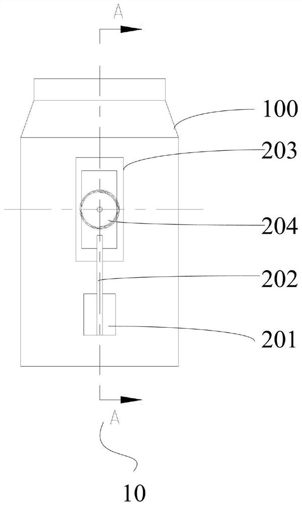
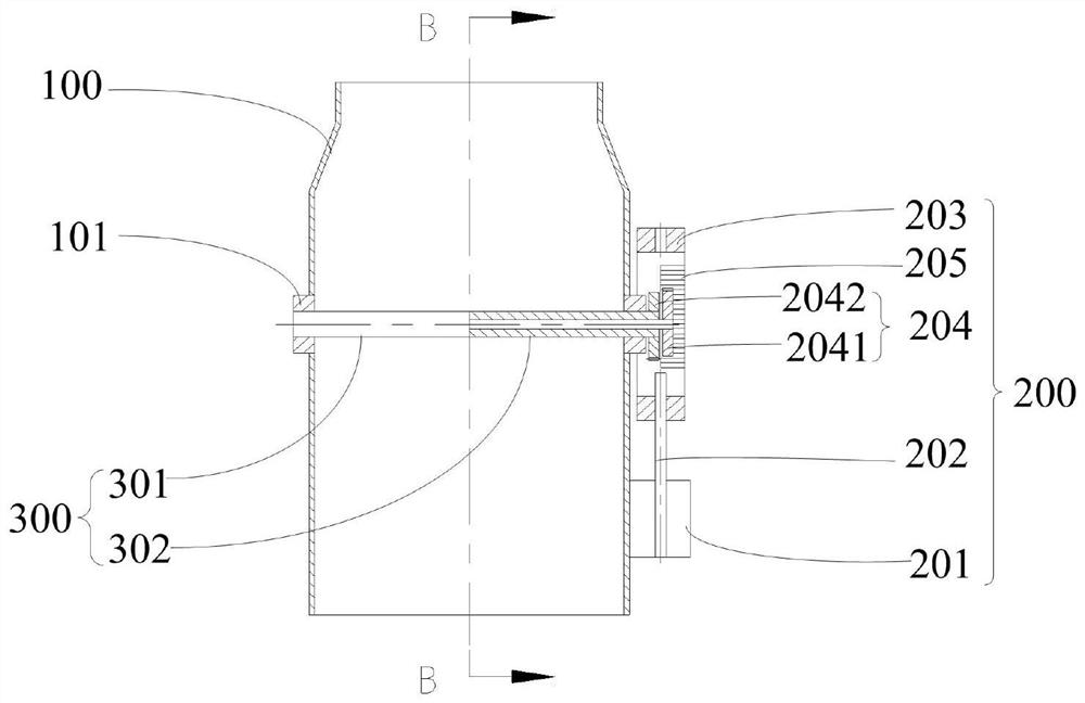
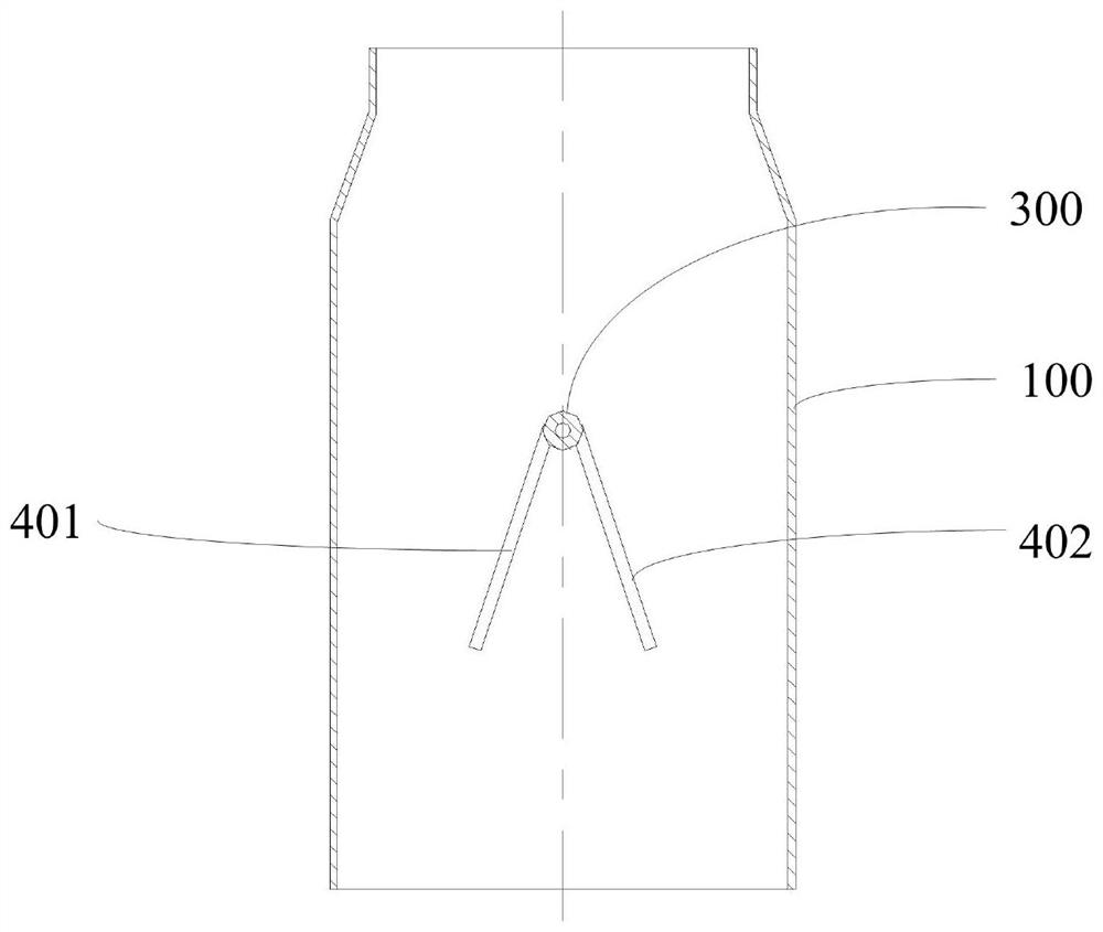
The invention relates to a pulverized coal concentration regulating valve comprising a shell, a driving part, a shaft and valve plates. The shell is vertically fixed between a coal mill and a pulverized coal pipeline. An air and powder mixture inlet is formed in the bottom of the shell. An air and powder mixture outlet is formed in the top of the shell. A pulverized coal concentration regulating cavity is formed between the air and powder mixture inlet and the air and powder mixture outlet. The driving part is connected to the side wall of the shell. A bearing seat is in the position, perpendicular to the direction of the driving part, of the side wall of the shell. One end of the shaft is driven by the driving part so as to rotate in the bearing seat. Two sets of valve plates are installed on the shaft and can form a closure region through opening and closing in the pulverized coal concentration regulating cavity so as to change the closure area in the pulverized coal concentration regulating cavity. The pulverized coal concentration regulating valve is disclosed, the driving part drives the shaft to rotate, the two valve plates are driven to form the closure region through opening and closing in the pulverized coal concentration regulating valve so as to change the closure area in the pulverized coal concentration regulating valve, and then the pulverized coal concentration in the pulverized coal pipeline is changed.

Description

technical field [0001] The invention relates to the technical field of pulverizing and grinding, and more specifically relates to a pulverized coal concentration regulating valve. Background technique [0002] Coal mill 500 and several pulverized coal pipelines 600 connected with it form pulverizing system, see attached Figure 9 , the pulverizing system is responsible for grinding the raw coal into coal powder with qualified fineness, and transporting it to the boiler 700 for combustion. The primary air and raw coal enter the coal mill 500 at the same time, and the primary air carries the pulverized coal into the pulverized coal separator in the pulverizer 500. After the coarse and fine powder is separated, the primary air continues to carry the pulverized coal into the pulverized coal pipeline 600. Until entering the boiler 700. In order to improve the combustion efficiency of the boiler 700 and the safety of the boiler operation, it is required that the pulverized coal f...

Claims


Application Information

Patent Timeline
Patent Type & Authority Applications(China)
IPC IPC(8): F16K1/22F16K1/36F16K1/32F16K31/04F16K31/54F16K27/02
CPCF16K1/2021F16K1/32F16K1/36F16K27/0209F16K31/041F16K31/54
Inventor 田航贺岚清
Owner 上海卡山科技股份有限公司
Learn More