
Heat pump unit

A technology for heat pump units and compressors, applied in heat pumps, refrigerators, compressors, etc., can solve problems such as poor methods and achieve the effect of improving the degree of intelligence

Pending Publication Date: 2021-01-15
QINGDAO HAIER AIR CONDITIONING ELECTRONICS CO LTD +1
View PDF0 Cites 0 Cited by
  • Summary
  • Abstract
  • Description
  • Claims
  • Application Information

AI Technical Summary

Problems solved by technology

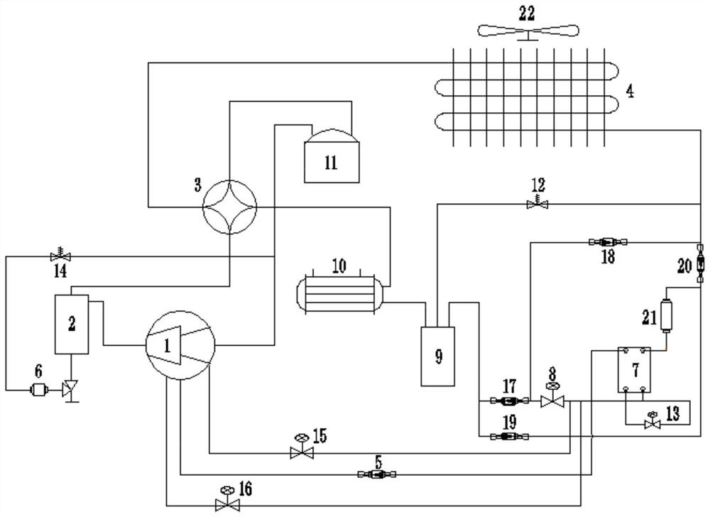
[0004] In order to solve the above-mentioned problems in the prior art, that is, in order to solve the problem that the existing heat pump unit has a poor way to work stably under the condition of low ambient temperature and high pressure ratio, the present invention provides a new heat pump unit , the heat pump unit includes a main circulation circuit and a liquid injection pipeline connected with the main circulation circuit; wherein, the main circulation circuit is provided with a compressor, a first heat exchanger, a throttling member and a second Two heat exchangers, in the heating mode, the first heat exchanger is used as an evaporator, the second heat exchanger is used as a condenser, and the throttling member is arranged between the first heat exchanger and the Between the second heat exchangers, one end of the liquid injection pipeline is connected to the compressor, and the other end of the liquid injection pipeline is connected between the first heat exchanger and the throttling member, so that the cooled heat exchange medium can be introduced into the compressor

Method used


Image

  • Heat pump unit

Examples


Embodiment Construction

[0019] Preferred embodiments of the present invention are described below with reference to the accompanying drawings. Those skilled in the art should understand that these embodiments are only used to explain the technical principles of the present invention, and are not intended to limit the protection scope of the present invention. Those skilled in the art can make adjustments as needed so as to adapt to specific applications.

[0020] It should be noted that, in the description of the present invention, the terms "upper", "lower", "left", "right", "front", "rear", "inner", "outer" etc. indicate directions or positions The terms of the relationship are based on the orientation or positional relationship shown in the drawings, which are for convenience of description only, and do not indicate or imply that the device or element must have a specific orientation, be constructed and operated in a specific orientation, and therefore cannot be interpreted as Limitations on the ...


PUM


Abstract

The invention belongs to the technical field of heat exchange, and particularly provides a heat pump unit. The heat pump unit aims at solving the problem that an existing heat pump unit adopts a poormode for stably working at a low environment temperature and a high pressure ratio. Therefore, the heat pump unit provided by the invention comprises a main circulation loop and a liquid spraying pipeline communicating with the main circulation loop, wherein a compressor, a first heat exchanger, a throttling component and a second heat exchanger which communicate with each other are arranged on the main circulation loop. In the heating mode, the first heat exchanger is used as an evaporator; the second heat exchanger is used as a condenser; the throttling component is arranged between the first heat exchanger and the second heat exchanger; one end of the liquid spraying pipeline is connected with the compressor, and the other end of the liquid spraying pipeline is connected between the first heat exchanger and the throttling component, so that a cooled heat exchange medium can be introduced into the compressor; the evaporation temperature of the compressor can be effectively reduced; and the cost can be effectively reduced when the heat pump unit is enabled to stably work at the low environment temperature and the high pressure ratio.

Description

technical field [0001] The invention belongs to the technical field of heat exchange, and specifically provides a heat pump unit. Background technique [0002] With the continuous improvement of people's living standards, people have also put forward higher and higher requirements for the living environment. In order to maintain a comfortable ambient temperature, air conditioners have become an essential device in people's lives. Specifically, most of the existing high-power air-conditioning equipment uses heat pump units. In order to effectively ensure that the heat pump units can work stably under the condition of low ambient temperature and high pressure ratio, the existing heat pump units usually adopt the following two methods: one method is Configure a two-stage compression system for the heat pump unit, that is, use a low-pressure stage compressor and a high-pressure stage compressor to work together to ensure the compression function. However, this method requires m...

Claims


Application Information

Patent Timeline
IPC IPC(8): F25B30/02F25B41/40F25B41/31F25B1/047
CPCF25B1/047F25B30/02F25B41/00F25B41/31F25B41/40
Inventor 谢吉培张洪亮李林徐志强赵雷刘乾坤
Owner QINGDAO HAIER AIR CONDITIONING ELECTRONICS CO LTD
Learn More