Optical proximity correction method

A technology of optical proximity correction and optical simulation, applied in optics, originals for opto-mechanical processing, instruments, etc., and can solve problems such as OPC graphics correction errors

Pending Publication Date: 2021-01-15
SHANGHAI HUALI MICROELECTRONICS CORP
View PDF0 Cites 4 Cited by
  • Summary
  • Abstract
  • Description
  • Claims
  • Application Information

AI Technical Summary

Problems solved by technology

[0004] The purpose of the present invention is to provide a method for optical proximity correction to solve the problem that the optical proximity correction of OPC graphics in the prior art is affected by grid segmentation and causes correction errors in OPC graphics

Method used


Image

  • Optical proximity correction method
  • Optical proximity correction method
  • Optical proximity correction method

Examples


Embodiment Construction

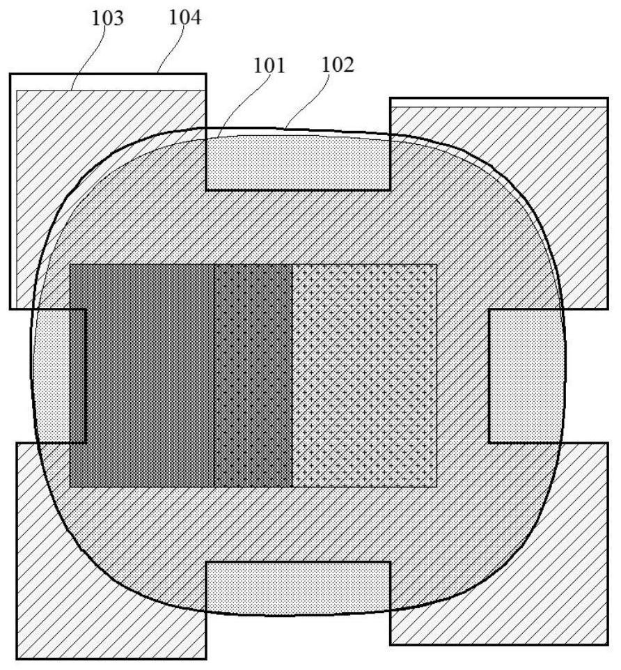
[0031] Please refer to figure 1 , in the prior art, OPC software is used to correct the OPC graphics of the memory chip, and after the OPC graphics are rasterized, the corrected graphics are obtained through correction. figure 1 Among them is a specific pattern in the memory chip, and its rasterized corrected pattern 104 is obtained after correction in the prior art, and optical simulation is performed on the corrected pattern 104 after rasterized correction to obtain a rasterized corrected pattern 104 Analog Graphics 102; however in figure 1 The target simulation figure 101 is the final figure required for optical simulation after correction. Compared with the target simulation figure 101 after rasterization correction, it can be seen that there is a slight deviation in the rasterization correction simulation figure 102 , it is due to correction errors in the rasterized corrected corrected graphic 104 that the rasterized corrected simulated graphic 102 deviates, and the targ...


PUM

PropertyMeasurementUnit
sizeaaaaaaaaaa

Abstract

The invention provides an optical proximity correction method. The method comprises the following steps: importing an OPC graph into OPC software, the OPC graph having a plurality of specific patterns; selecting any specific graph in the OPC graph, performing optical simulation on the specific graph to obtain a simulation graph, overlapping the simulation graph with the specific graph, and cuttingtwo adjacent sides of the specific graph into n sections, n being greater than or equal to 3; selecting one or two of the n sections as operation sections, and calculating the minimum distance between each operation section and the simulation graph; and according to the minimum distance, moving the corresponding operation section by a unit movement amount, carrying out optical simulation once every time the operation section is moved so as to update the simulation graph, and after the simulation graph is updated every time, recalculating the minimum distance between each operation section andthe simulation graph. According to the method, the problem that in the prior art, optical proximity correction of the OPC graph is affected by grid segmentation, and consequently correction errors exist in the OPC graph is solved.

Description

technical field [0001] The invention relates to the technical field of semiconductors, in particular to an optical proximity correction method. Background technique [0002] With the shrinking of the size of semiconductor devices, the requirements for the existing process are getting higher and higher, and the requirements for the consistency of the key dimensions of the device are becoming more and more stringent. The lower limit of the node design size is even tighter than the lower limit of the size. There must be a certain error range in the actual imaging process from the designed OPC pattern of the memory chip to the pattern, so it is necessary to correct the OPC pattern of the memory chip. [0003] When using OPC software to correct OPC graphics, in order to speed up the processing, the OPC software will rasterize the OPC graphics, and then correct the sub-modules of the rasterized OPC graphics synchronously, and then convert the sub-modules of OPC graphics Integrat...

Claims


Application Information

Patent Timeline
Patent Type & Authority Applications(China)
IPC IPC(8): G03F1/36
CPCG03F1/36
Inventor 顾婷婷张浩陈翰宋康
Owner SHANGHAI HUALI MICROELECTRONICS CORP
Why Eureka
Try Eureka