Array substrate and manufacturing method thereof, display panel and display device

An array substrate and plane technology, which is applied in the fields of array substrate and its manufacturing method, display panel, and display device, can solve the problems of poor lyophilicity, difference in brightness uniformity, uneven film thickness between pixels, etc., and achieve improved film formation. Uniformity, wide application prospects, and the effect of improving fluidity

Active Publication Date: 2021-01-15
BOE TECH GRP CO LTD
View PDF6 Cites 1 Cited by
  • Summary
  • Abstract
  • Description
  • Claims
  • Application Information

AI Technical Summary

Problems solved by technology

[0002] When using inkjet printing technology to prepare OLED devices, due to the error in the amount of ink ejected between multiple nozzles, the film thickness between pixels will be uneven, which will cause differences in brightness uniformity when reflected on the light-emitting device.
In the prior art, the problem of uniformity of film formation in the pixel is improved by connecting the sub-pixels of the same color in each column, but the following problem is found in the process of actually manufacturing the backplane, the pixels used to connect the sub-pixels of the same color Due to partial etching in the limited area, there will be a problem of poor lyophilicity in the corresponding position, which will cause the ink of the Unicom structure to be unable to communicate in the partially etched area, thus affecting the uniformity of the film between pixels due to the inability to mix the ink uniformly

Method used


Image

  • Array substrate and manufacturing method thereof, display panel and display device
  • Array substrate and manufacturing method thereof, display panel and display device
  • Array substrate and manufacturing method thereof, display panel and display device

Examples


Embodiment Construction

[0027] In order to illustrate the present invention more clearly, the present invention will be further described below in conjunction with preferred embodiments and accompanying drawings. Similar parts in the figures are denoted by the same reference numerals. Those skilled in the art should understand that the content specifically described below is illustrative rather than restrictive, and should not limit the protection scope of the present invention.

[0028] Unless otherwise defined, the technical terms or scientific terms used in the present invention shall have the usual meanings understood by those skilled in the art to which the present invention belongs. "First", "second" and similar words used in the present invention do not indicate any order, quantity or importance, but are only used to distinguish different components. "Comprising" or "comprising" and similar words mean that the elements or items appearing before the word include the elements or items listed af...


PUM


Abstract

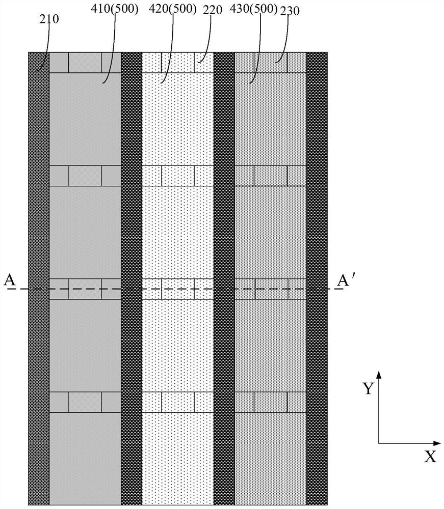
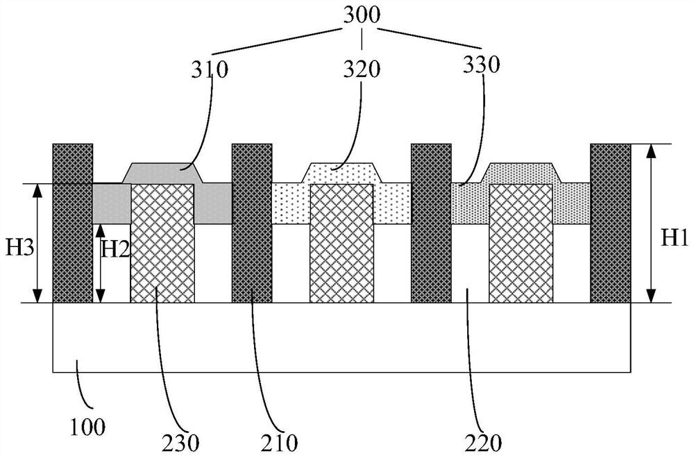
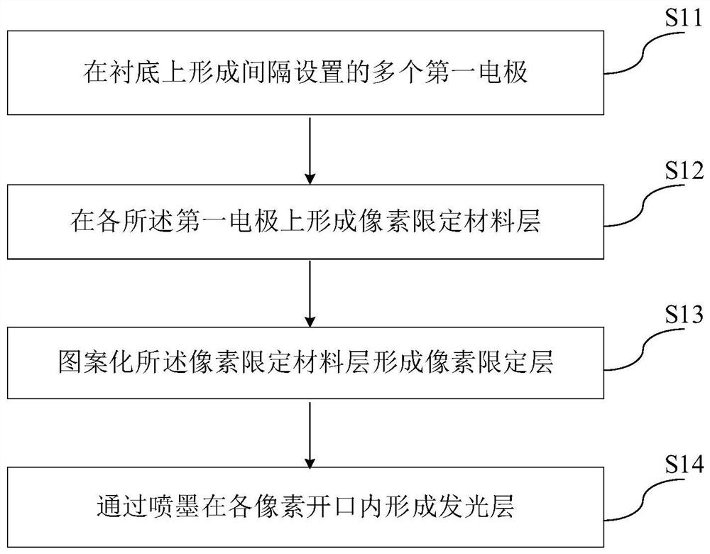
The invention discloses an array substrate and a manufacturing method thereof, a display panel and a display device. The array substrate comprises a plurality of first electrodes arranged on a substrate at intervals, a pixel defining layer disposed on the first electrodes and a light emitting layer, wherein the pixel defining layer defines a plurality of pixel openings; the light emitting layer isdisposed within the pixel openings; the pixel defining layer includes a first sub-portion, a second sub-portion and a third sub-portion; the first sub-portion is disposed between two adjacent pixel openings of the light emitting layer of different colors, and the first sub-portion has a first height; and the second sub-portion and the third sub-portion are arranged between the two adjacent pixelopenings of the light-emitting layer with the same color, the second sub-portion is located between the first sub-portion and the third sub-portion, the second sub-portion has a second height, the third sub-portion has a third height, and the third height is smaller than the first height and larger than the second height. According to the invention, the second sub-portion with the third height isarranged between the third sub-portion with the second height and the first sub-portion with the first height so that the fluidity of ink in pixels with the same color is improved, and the film forming uniformity is increased.

Description

technical field [0001] The present invention relates to the field of display technology, in particular to an array substrate and a manufacturing method thereof, a display panel, and a display device. Background technique [0002] When using inkjet printing technology to prepare OLED devices, due to the error in the amount of ink ejected between multiple nozzles, the film thickness between pixels will be uneven, which will cause differences in brightness uniformity when reflected on the light-emitting device. In the prior art, the problem of uniformity of film formation in the pixel is improved by connecting the sub-pixels of the same color in each column, but the following problem is found in the process of actually manufacturing the backplane, the pixels used to connect the sub-pixels of the same color Due to partial etching in the limited area, there will be a problem of poor lyophilicity in the corresponding position, which will cause the ink of the connected structure to...

Claims


Application Information

Patent Timeline
Patent Type & Authority Applications(China)
IPC IPC(8): H01L27/32H01L51/56
CPCH10K59/122H10K59/1201H10K71/00H10K59/35H10K2102/351H10K50/84
Inventor 崔颖
Owner BOE TECH GRP CO LTD
Why Eureka
Try Eureka