

Flip type orthodontic bracket
An orthodontic bracket, clamshell technology, applied in brackets, arch wires, etc., can solve the inevitable pressure and damage of teeth and brackets, affect the accurate expression of bracket preset data, and inconvenient to insert or remove arch wires and other problems to achieve the effect of reducing the accommodation space of the arch wire, enhancing the correction effect, and shortening the operation time.
- Summary
- Abstract
- Description
- Claims
- Application Information
AI Technical Summary
Problems solved by technology
Method used
Image

Examples
Embodiment 1
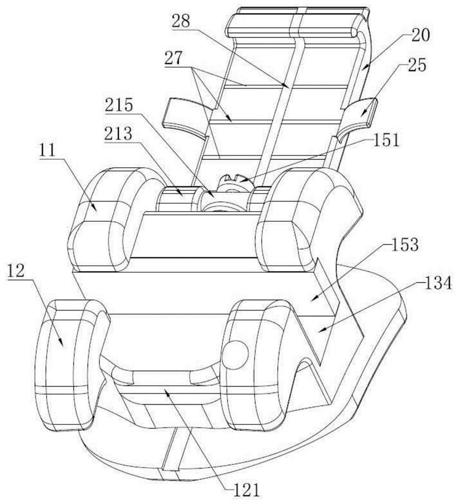
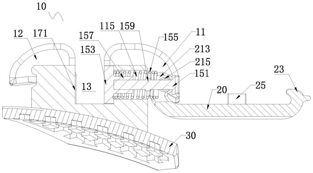
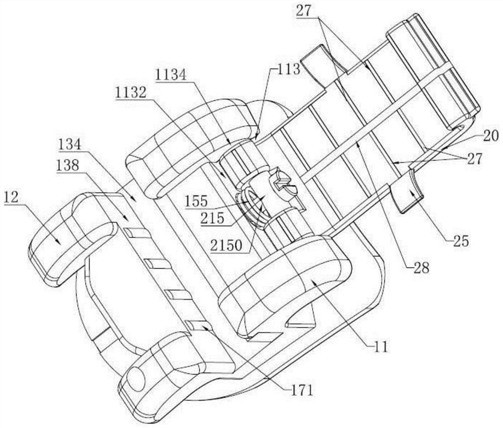
[0052] Such as Figure 1-Figure 6 As shown, the flip-top orthodontic bracket of the first embodiment includes a bracket main body 10 , a flip cover 20 and a bottom plate 30 . The bottom plate 30 is disposed on the bottom of the bracket main body 10 for bonding with the tooth surface.
[0053] Specifically, the bracket main body 10 is provided with an archwire slot 13, a limiting mechanism and a sliding part. The archwire slot 13 divides the bracket main body 10 into two, including a first bracket wing 11 protruding in the maxillary-gingiva direction and a A second bracket wing 12 protruding in the gingival-jaw direction.
[0054] Wherein, the middle part of the gingival surface of the first bracket wing 11 is recessed to form a receiving groove 113 , and the receiving groove 113 accommodates the rotating part of the flip cover 20 . The sinking surface of the receiving tank 113 is the bottom surface 1132 of the receiving tank 113 . The two ends of the receiving groove 113 in...
Embodiment 2
[0076] Such as Figure 7-Figure 10 As shown, the flip-top orthodontic bracket of the second embodiment includes a bracket main body 410, a flip cover 420 and a bottom plate. The bottom plate is arranged on the bottom of the bracket main body 410 for bonding with the tooth surface.
[0077] Specifically, the bracket main body 410 is provided with an archwire slot 413 and a limiting mechanism. The archwire slot 413 divides the bracket main body 410 into two, including a first bracket wing 411 protruding in the jaw-gingival direction and a first bracket wing 411 protruding toward the gum-gingiva direction. A second bracket wing 412 protruding in the jaw direction.
[0078] Wherein, the middle part of the gingival surface of the first bracket wing 411 is recessed to form a receiving groove, and the receiving groove accommodates the rotating part 421 of the flip cover 420 . The second bracket wing 412 is provided with a fastening position 4121 and an accommodating cavity 4123 for...
Embodiment 3
[0093] Such as Figure 11 As shown, the flip-type orthodontic bracket of Embodiment 3 is substantially the same as that of Embodiment 2, and the difference lies in that the driving member of Embodiment 3 is different from that of Embodiment 2.
[0094] The driving member of embodiment 3 is a pressing block 5151, a connecting rod 5155 and a return spring 5157. The pressing block 5151 is accommodated in the accommodation cavity 5123 of the bracket main body, and a return spring 5157 is arranged between the pressing block 5151 and the bottom of the accommodation cavity 5123. The briquetting block 5151 is maintained at the initial position, the tongue side of the briquetting block 5151 is an inclined plane, and the surface where one end of the connecting rod 5155 is in contact with the incline of the pressing block 5151 is also an inclined plane, and the pressing block 5151 matches and contacts the connecting rod 5155, and the connecting rod The other end of 5155 is connected with...
PUM
 Abstract
Description
Claims
Application Information