Intelligent manufacturing production machining equipment
A kind of processing equipment and intelligent manufacturing technology, which is applied in metal processing and other directions, can solve the problems of cumbersome fixing and dismounting of cutting knives, uncertain clamping degree of cut materials, etc.
- Summary
- Abstract
- Description
- Claims
- Application Information
AI Technical Summary
Problems solved by technology
Method used
Image

Examples
specific Embodiment approach 1
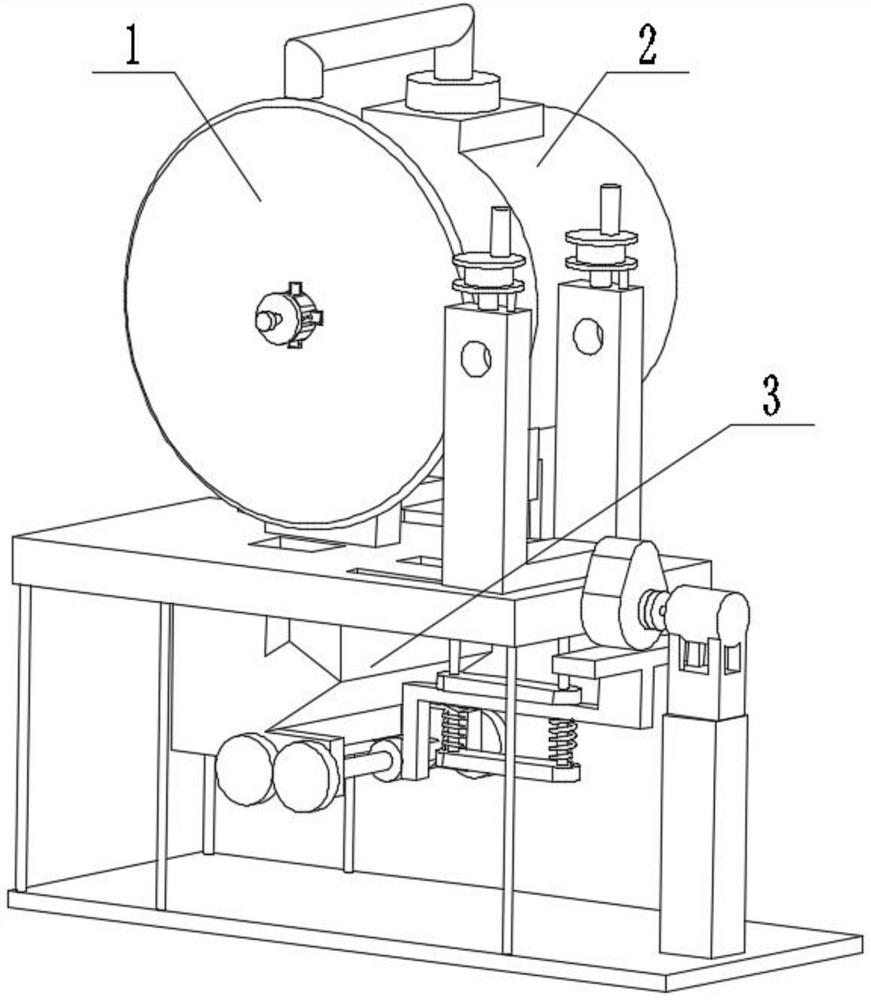
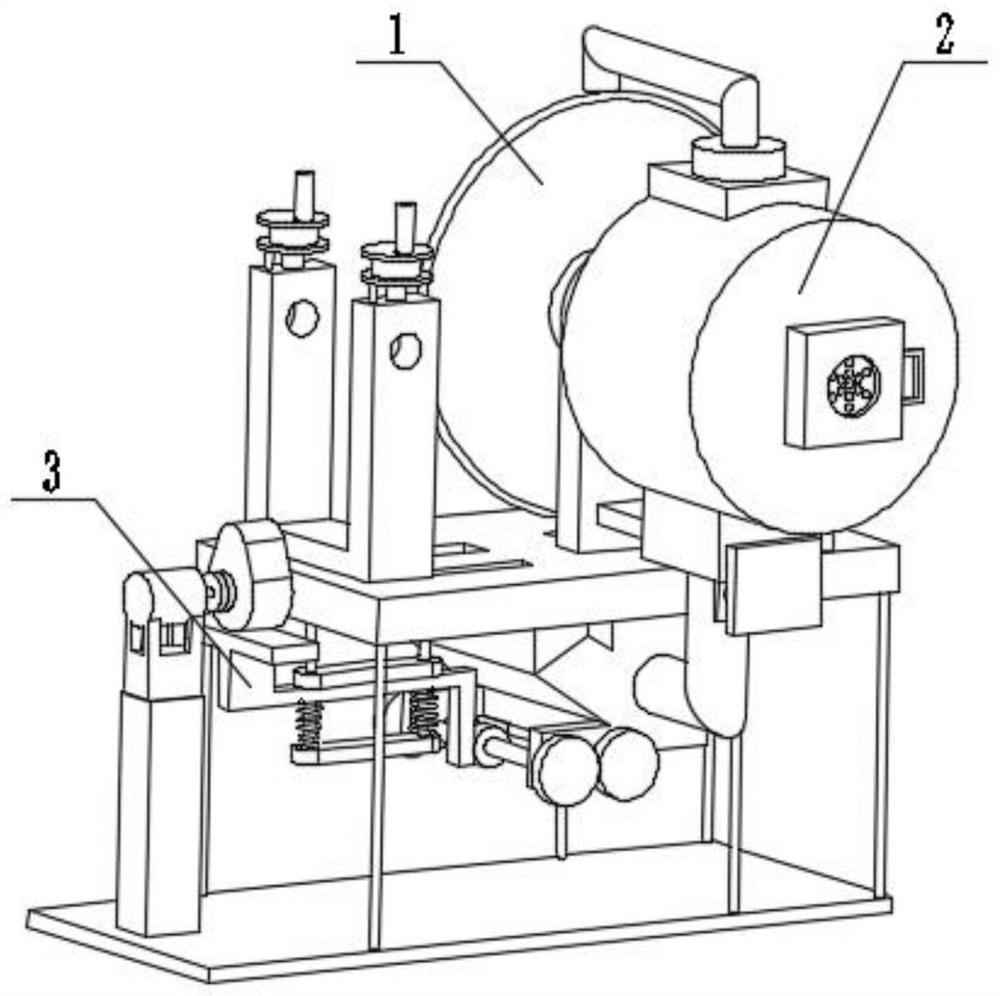
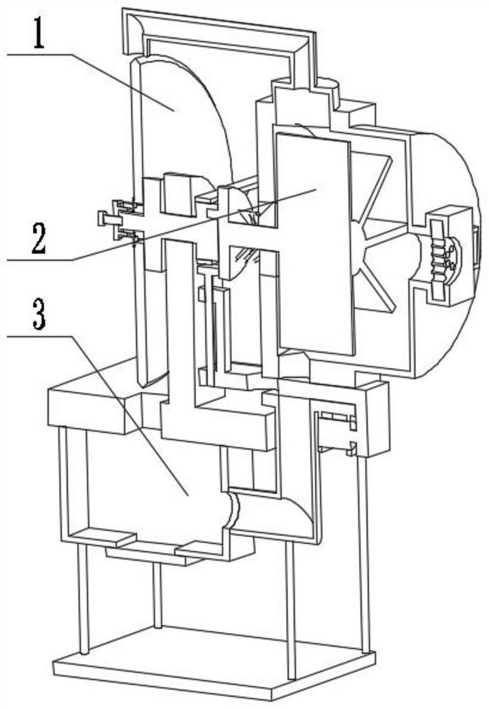
[0031] Combine below figure 1 , figure 2 , image 3 , Figure 4 , Figure 5 , Figure 6 , Figure 7 , Figure 8 , Figure 9 , Figure 10 , Figure 11 , Figure 12 , Figure 13 , Figure 14 , Figure 15 , Figure 16 Describe this embodiment. The present invention relates to a processing equipment, more specifically, an intelligent manufacturing production and processing equipment, including a cutting mechanism 1, a two-way wind mechanism 2, and a linkage collection mechanism 3. The equipment can easily disassemble the cutting knife, and the equipment can Switch between heat dissipation and dust removal modes, the equipment can collect waste residue, and the equipment can discharge materials intermittently.
[0032]The cutting mechanism 1 is connected with the two-way wind mechanism 2 , and the cutting mechanism 1 is connected with the linkage collection mechanism 3 .
specific Embodiment approach 2
[0034] Combine below figure 1 , figure 2 , image 3 , Figure 4 , Figure 5 , Figure 6 , Figure 7 , Figure 8 , Figure 9 , Figure 10 , Figure 11 , Figure 12 , Figure 13 , Figure 14 , Figure 15 , Figure 16 This embodiment will be described. This embodiment will further describe the first embodiment. The cutting mechanism 1 includes a handle screw 1-1, a connection plate 1-2, a threaded hole 1-3, a ladder slide rod 1-4, a hinged Seat 1-5, hinge plate 1-6, hinge plate I1-7 with cylindrical protrusion, slide groove 1-8, servo motor 1-9, motor pulley 1-10, belt 1-11, cutting knife 1-12, Handwheel with lead screw 1-13, threaded hole 1-14, scale ladder rod 1-15, ladder hole 1-16, insertion hole 1-17, moving seat 1-18, limit chute 1-19, limit Chute I1-20, cam 1-21, servo motor I1-22, limit plate I1-23, vertical slide bar 1-24, spring 1-25, lower limit plate 1-26, platform 1 with leakage channel -27, drive hole 1-28, belt shaft drive pulley 1-29, shaft coupli...
specific Embodiment approach 3
[0036] Combine below figure 1 , figure 2 , image 3 , Figure 4 , Figure 5 , Figure 6 , Figure 7 , Figure 8 , Figure 9 , Figure 10 , Figure 11 , Figure 12 , Figure 13 , Figure 14 , Figure 15 , Figure 16 Describe this embodiment, this embodiment will further explain the first embodiment, the two-way wind mechanism 2 includes a connecting pipe 2-1, a hydraulic cylinder support 2-2, a hydraulic cylinder 2-3, an L-shaped plate 2-4, a box Body 2-5, filter plate 2-6, filter plate groove 2-7, air duct 2-8, shaft with special-shaped hole 2-9, spring 2-10, special-shaped shaft 2-11, limit plate with protrusion 2 -12, belt shaft pulley 2-13, bearing seat 2-14, leakage outlet I2-15, filter opening 2-16, chute A2-17, wind wheel 2-18, connecting pipe 2-1 and box body 2- 5 are connected and connected, the hydraulic cylinder support 2-2 is connected with the box body 2-5, the hydraulic cylinder support 2-2 is connected with the hydraulic cylinder 2-3, the hydrauli...
PUM
 Abstract
Description
Claims
Application Information
 - R&D Engineer
- R&D Manager
- IP Professional
- Industry Leading Data Capabilities
- Powerful AI technology
- Patent DNA Extraction
Browse by: Latest US Patents, China's latest patents, Technical Efficacy Thesaurus, Application Domain, Technology Topic.
© 2024 PatSnap. All rights reserved.Legal|Privacy policy|Modern Slavery Act Transparency Statement|Sitemap